** Optimizing Industrial Efficiency: The Critical Role of Boiler High-Temperature Induced Draft Fans in Modern Thermal Systems

Table of Contents / Guide
- Introduction: Understanding the Core Function
- Technical Specifications and Operating Principles
- Common Challenges: Heat, Wear, and Vibration Control
- Key Design Features for High-Temperature Resistance
- Performance Optimization and Energy Savings
- Frequently Asked Questions (FAQ)
- Conclusion: Future Trends and Maintenance Best Practices
Introduction: Understanding the Core Function
In any industrial boiler system, the high-temperature induced draft fan (ID fan) is the unsung hero of combustion efficiency. Unlike forced draft fans that push air into the furnace, the ID fan draws flue gases out of the boiler, creating negative pressure that ensures safe combustion and prevents backflow of hot gases into the working environment. This process is especially demanding when the gas temperature exceeds 250°C, often reaching 350–400°C in coal, biomass, or waste-to-energy plants. A well-optimized ID fan directly impacts fuel consumption, emissions compliance, and equipment longevity. For site operators performing a wind turbine maintenance inspection, the same principle of airflow management applies — both systems rely on robust fan designs to handle extreme conditions.
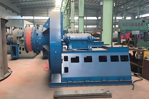
Technical Specifications and Operating Principles
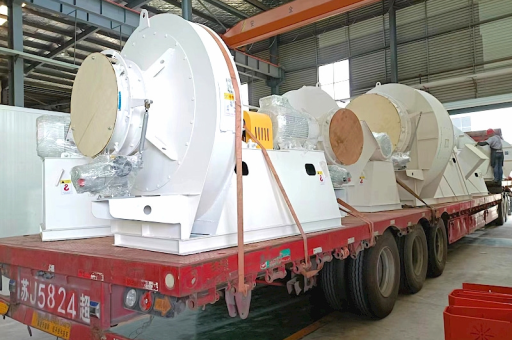
Modern boiler high-temperature induced draft fans operate at capacities ranging from 50,000 to 800,000 m³/h, depending on boiler size and fuel type. The most common types include centrifugal radial-blade fans and backward-curved blade fans. Key operating parameters include:
- Temperature range: Typically 250°C to 450°C, with special designs reaching up to 650°C.
- Pressure differential: 2,000 to 8,000 Pa, depending on system resistance.
- Rotational speed: Usually 750 to 1,500 RPM, controlled via variable frequency drives (VFDs).
- Material selection: The impeller is often crafted from wear-resistant steel alloys or coated with ceramic layers to resist erosion and thermal fatigue.
The principle of operation relies on the centrifugal force generated by the rotating impeller, which accelerates the flue gas outward into the volute casing, converting kinetic energy into pressure energy. This pressure overcomes the resistance of ductwork, scrubbers, and chimney stacks.
Common Challenges: Heat, Wear, and Vibration Control
High-temperature environments present three major threats: thermal expansion, abrasive wear, and vibration-induced fatigue.
- Thermal expansion: Differential expansion between the shaft, impeller, and casing can cause bearing misalignment. To mitigate this, expansion joints and cooling shafts are employed.
- Abrasive wear: Ash and particulates in flue gas erode blade surfaces over time. Coatings like tungsten carbide or Stellite are applied to extend service life.
- Vibration: Imbalance from uneven ash buildup or bearing wear leads to excessive vibration. Regular dynamic balancing and condition monitoring are essential. If a wind turbine maintenance team notices similar vibration patterns in a turbine nacelle’s cooling fan, they often use the same root cause analysis method: spectral analysis and balancing.
Key Design Features for High-Temperature Resistance
To ensure reliability under extreme heat, manufacturers incorporate several advanced design features:
- Shaft cooling: A dedicated cooling fan or water jacket around the shaft reduces heat transfer to bearings.
- Inlet box and turning vanes: These guide the gas smoothly into the impeller, reducing turbulence and localized hotspots.
- Labyrinth seals: Prevent hot gas leakage into the bearing housing, maintaining lubricant integrity.
- Double-stage design: For very high pressure or temperature, two fans can be placed in series or parallel, splitting the load and thermal stress.
- Material upgrades: Stainless steel (304L, 316L) or duplex stainless steel is used for high-temperature sections; Inconel alloys are specified for extreme cases above 500°C.
Performance Optimization and Energy Savings
The energy consumption of an ID fan can represent 20–30% of total boiler auxiliary power. Optimizing its performance yields significant cost savings. Strategies include:
- Variable frequency drive (VFD) installation: Adjusting fan speed to match actual boiler load reduces electricity use by 30–50% compared to damper control.
- Inlet vane control: Pre-swirling the incoming gas reduces required impeller work.
- Regular blade cleaning: Preventing ash buildup maintains aerodynamic efficiency and reduces unbalance.
- Computational fluid dynamics (CFD) modeling: Simulation tools predict flow patterns and identify areas where erosion or recirculation may occur, allowing design improvements before fabrication.
For reference, in a wind turbine maintenance context, a similar approach — using predictive analytics to adjust cooling fan speed based on ambient temperature — can extend component life by 15–20%.
Frequently Asked Questions (FAQ)
Q1: What is the difference between a forced draft fan and an induced draft fan? A: A forced draft fan pushes ambient air into the burner, whereas an induced draft fan extracts hot flue gas from the boiler. The ID fan must handle higher temperatures and often contains more airborne particulates.
Q2: How often should a boiler high-temperature induced draft fan be inspected? A: Monthly visual inspections are recommended for vibration, noise, and bearing temperature. A full teardown inspection — including blade thickness measurement and crack detection — should be performed every 12 to 18 months, depending on operating hours and fuel type.
Q3: Can a standard fan withstand 400°C continuously? A: Not without special design modifications. Standard carbon steel fans deform above 350°C. For continuous 400°C operation, the fan must be built from heat-resistant alloys and include shaft cooling and thermal gap compensation.
Q4: What sensors are typically used for monitoring an ID fan? A: Common sensors include bearing vibration accelerometers, thermocouples for bearing and casing temperature, and pressure transmitters across the fan inlet and outlet. Some advanced systems also use infrared cameras to detect casing hotspots.
Q5: How does ash buildup affect performance? A: Ash accumulation on blades increases the impeller mass and changes its aerodynamic profile. This leads to reduced efficiency, higher current draw, and increased vibration. In severe cases, imbalance can cause catastrophic bearing failure.
Conclusion: Future Trends and Maintenance Best Practices
The boiler high-temperature induced draft fan will continue to evolve with stricter emissions regulations and the push toward carbon neutrality. Key trends include the integration of smart sensors and IoT-based condition monitoring, enabling predictive maintenance that prevents unplanned downtime. Advanced coatings and additive manufacturing are also allowing more complex blade geometries that withstand higher temperatures with less material.
For maintenance best practices, always keep these in mind:
- Monitor bearing vibration trends and set alarm thresholds at 4.5 mm/s RMS.
- Implement an oil analysis program for bearing lubrication.
- Use thermal imaging to detect casing hotspots before they cause failure.
- Ensure proper alignment and balance after every repair.
Whether you manage a coal-fired plant, a biomass facility, or even a wind turbine maintenance operation for nacelle cooling systems, the fundamental lesson is the same: a well-designed, well-maintained fan system is the backbone of reliable thermal performance. By understanding the unique demands of high-temperature gas handling, engineers can significantly improve uptime, reduce energy costs, and extend equipment life.