This article's table of contents introduction:

- Core Function
- Key Specifications (Data Sheet Essentials)
- Common Fan Types & Configurations
- Critical Design Features for Furnaces
- The "High Pressure" Challenge
- Safety & Compliance
- Common Problems & Troubleshooting
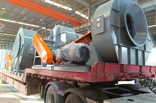
- Manufacturer Examples
- Final Recommendation
This is a highly specialized topic. When referring to Industrial Furnace Combustion Support High-Pressure Fans, we are usually talking about Forced Draft (FD) fans or specialized Combustion Air Blowers.
These fans are critical for safety, efficiency, and emissions control. Below is a detailed breakdown of the specifications, types, challenges, and selection criteria for these fans.
Core Function
The primary job of these fans is to overcome the resistance of the furnace, burner, and heat exchanger to deliver the precise volume of air required for stoichiometric combustion (the ideal fuel-to-air ratio).
Key Specifications (Data Sheet Essentials)
When sourcing or specifying these fans, look for these parameters:
- Pressure (Static or Total): Typically 20" w.g. (5 kPa) to 60" w.g. (15 kPa) or higher. Low-pressure fans (under 10" w.g.) are usually insufficient for modern, high-efficiency burners.
- Air Volume (CFM / m³/hr): Calculated based on fuel type (gas, oil, coal, biomass) and furnace heat release.
- Temperature: Standard is ambient (-20°C to 40°C). If pre-heated combustion air is used (waste heat recovery), you need a Hot Air Fan rated for 150°C to 400°C.
- Material: Carbon steel is standard. For corrosive atmospheres (e.g., sulfur in fuel), 316L Stainless Steel or coatings are required.
- Drive: Direct drive (motor shaft mounted) vs. Belt drive (allows speed/RPM adjustment via pulley changes).
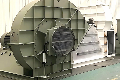
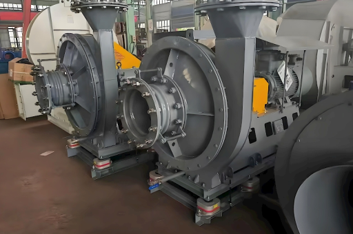
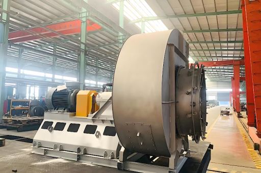
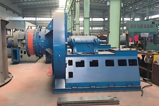
Common Fan Types & Configurations
| Fan Type | Best For | Advantages | Disadvantages |
|---|---|---|---|
| Centrifugal (Radial) | Most industrial furnaces | High pressure, robust, handles dirty air | Larger footprint, lower efficiency than airfoil |
| Backward Inclined (BI) | Clean air / gas applications | High efficiency (85%+), non-overloading power curve | Sensitive to erosion |
| Airfoil (AF) | Large furnaces, highest efficiency | Very quiet, highest efficiency (90%+), lightweight | Expensive, fragile blades (not for dirty air) |
| Forward Curved (FC) | Smaller units / lower pressure | High volume/low pressure, compact | Lower efficiency, motor can overload if static pressure drops |
For combustion support: Backward Inclined Centrifugal is the industry workhorse.
Critical Design Features for Furnaces
- VFD (Variable Frequency Drive): Almost mandatory today. Allows precise air/fuel ratio control, soft start (reduces electrical stress), and energy savings (50% speed = 12.5% power).
- Inlet Box & Dampers: Modulating inlet vanes or outlet dampers to control air flow when VFDs are not used.
- Sound Attenuation: Furnace areas are loud. Fans often require silencers on the inlet and discharge.
- Spark-Resistant Construction: AMCA Type A or B (non-ferrous impeller or non-sparking ring) is often required for safety with fuel gases.
- Bearing Design: High ambient temperatures require external bearings with cooling fins or even water cooling if proximity to furnace radiant heat is a risk.
The "High Pressure" Challenge
Unlike HVAC fans, high-pressure here means:
- Discharge velocity: 3,000 to 5,000 ft/min (15–25 m/s) to penetrate the flame front.
- Turndown ratio: The fan must maintain stable pressure at very low flow (e.g., 10% load) without surging.
- Sealing: Shaft seals must prevent hot flue gas leakage back into the bearing housing.
Safety & Compliance
- NFPA 86 (Standard for Ovens and Furnaces): Requires safety interlocks (air flow proving switches) to prevent fuel flow if fan fails.
- Purge Cycle: Before ignition, the fan must run for a specific time (usually 4–5 air changes) to clear any unburnt fuel from the furnace.
- Explosion Proof (ATEX / NEC): If the fan handles fuel gas (e.g., pre-mix burners) or is located in a classified area, the motor, wiring, and impeller must be explosion-proof.
Common Problems & Troubleshooting
| Symptom | Likely Cause | Solution |
|---|---|---|
| Low air volume | Clogged inlet filter, VFD fault, belt slip, backward rotation (3-phase phasing) | Check filters, verify VFD Hz, check rotation arrow, tighten belts. |
| Vibration | Impeller imbalance (dirt buildup or erosion), bearing wear, resonance | Clean impeller, balance rotor, check baseplate rigidity. |
| Motor Overheating | Running too far left on curve (stall), voltage imbalance, high ambient temp | Check system resistance vs. fan curve, add cooling duct. |
| Surge / Stall | System resistance too high, damper closed too far | Open dampers, check for blocked duct, possibly upsizing fan. |
| Noise increase | Damper causing turbulence, cavitation (if near duct restrictions), bearing failure | Adjust damper position, install turning vanes, replace bearings. |
Manufacturer Examples
- New York Blower (USA)
- Howden / Chart Industries (Global)
- Robinson Fans (USA)
- Greenheck (Industrial Series)
- Cincinnati Fan (Heavy Duty Line)
- Siemens / Fläkt Woods (Europe)
Final Recommendation
For a high-pressure combustion support fan:
- Specify Backward Inclined Centrifugal or Radial type.
- Run on a VFD.
- Include AMCA Spark-Resistant construction.
- Ensure NFPA 86 air proving switch is integrated.
- Request a fan curve from the manufacturer showing the operating point.
Note: Always consult the burner manufacturer’s manual for exact air pressure and volume requirements. Undersizing leads to incomplete combustion and CO emissions; oversizing creates flame instability and higher NOx.