This article's table of contents introduction:

- What is an Induced Draft Fan?
- Location in the System (The Flow Path)
- How it Works (The Key Concept: Negative Pressure)
- Types of ID Fans
- Key Components
- Common Problems & Challenges
- ID Fan vs. FD Fan (Quick Comparison)
- Safety & Operation
- Summary
This is a comprehensive explanation of the Boiler Induced Draft (ID) Fan, covering its function, location, working principle, types, and common issues.
In a power plant or industrial boiler system, the Induced Draft Fan is the final piece of the air and flue gas path. Think of it as the "suction" or "exhaust" fan.
What is an Induced Draft Fan?
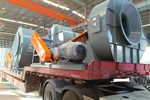
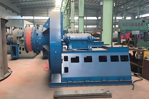
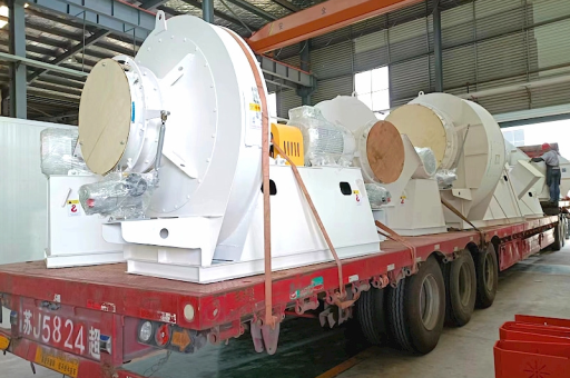
The ID Fan is a large, heavy-duty fan located after the boiler, air heater, and dust collector (ESP or baghouse). Its primary job is to pull flue gases (exhaust gases) out of the boiler furnace and through the pollution control equipment, finally discharging them up the chimney (stack).
Location in the System (The Flow Path)
To understand the ID fan, you need the order of equipment:
- Forced Draft (FD) Fan: Pushes fresh air into the furnace.
- Boiler Furnace: Fuel burns, creating hot flue gas.
- Air Heater: Recovers heat from flue gas to preheat incoming air.
- Dust Collector (ESP/Baghouse): Removes fly ash from the gas.
- Induced Draft (ID) Fan: Pulls the cleaned gas through.
- Chimney (Stack): Releases gas to the atmosphere.
How it Works (The Key Concept: Negative Pressure)
The ID fan creates a negative pressure (vacuum/draft) inside the boiler furnace.
- Why is this important? It ensures that if there are any leaks in the boiler casing, air leaks into the furnace (safe), instead of hot, toxic flue gases leaking out into the boiler room (dangerous for personnel).
- The Balance: The FD fan pushes air in, while the ID fan pulls gas out. The ID fan is always pulling slightly more than the FD fan is pushing, maintaining a slight vacuum in the furnace (typically -5 to -15 mmWC or similar depending on the boiler type).
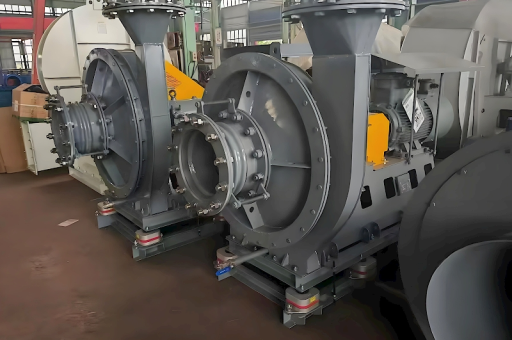
Types of ID Fans
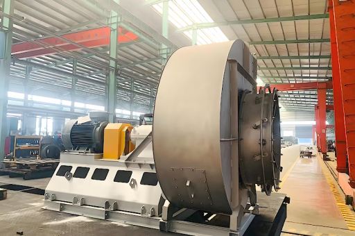
- Centrifugal Fan (Most Common): Used for high static pressure and moderate flow. The most common type for large industrial boilers.
- Radial (Paddle Wheel): Very robust, handles dusty gases well (common upstream of ESPs in older plants).
- Backward Curved: More efficient, but blades can wear faster with abrasive particles.
- Axial Fan: Used in applications requiring very high flow rates but lower pressure (less common for main boiler ID, more for cooling towers or gas turbines).
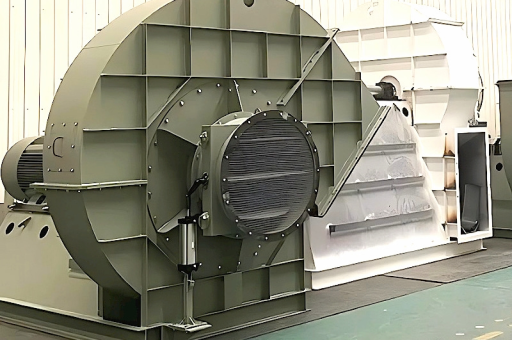
Key Components
- Rotor/Impeller: The spinning blades. Often made of abrasion-resistant steel and "roofed" (covered) to prevent dust build-up.
- Shaft & Bearings: Must handle high temperatures and heavy loads. Often water-cooled or oil-lubricated.
- Inlet Guide Vanes (IGVs) / Dampers: Used to control the fan's airflow. By changing the pitch of the IGVs, you can modulate the fan's suction capacity without using inefficient discharge dampers.
- Motor & Coupling: Usually a large AC induction motor (up to several MW).
- Variable Frequency Drive (VFD): Modern standard. Allows precise speed control of the fan motor, saving significant energy compared to dampers.
Common Problems & Challenges
ID Fans operate in a very harsh environment. The most common issues are:
| Problem | Cause | Effect | Solution |
|---|---|---|---|
| Erosion / Wear | Fly ash particles hitting the blades at high velocity (especially after ESP failure). | Imbalance, vibration, reduced efficiency, blade failure. | Hard-facing blades, wear plates, ceramic coatings, maintaining ESP efficiency. |
| Vibration | Blade erosion, dust build-up (uneven balance), bearing failure, or misalignment. | Catastrophic failure, damage to ducts & supports. | Regular balance checks, cleaning schedule, vibration monitoring system. |
| High Temperature | Bypass of air heater, boiler upset conditions. | Bearing failure, warping of the impeller, thermal expansion issues. | High-temperature alloy materials, cooling systems, interlock to trip on high temp. |
| Corrosion | Moisture in flue gas (especially below dew point) reacting with sulfur (acid rain). | Pitting of blades and casing. | Operating above acid dew point, using corrosion-resistant coatings (e.g., rubber lining if wet FGD is downstream). |
| Stall / Surge | Operating far from the design point (low flow, high pressure). | Violent pressure oscillations, loud noise, mechanical damage. | Avoid low-load operation, use proper control logic (VFD/IGV). |
ID Fan vs. FD Fan (Quick Comparison)
| Feature | ID Fan | FD Fan |
|---|---|---|
| Location | After the boiler (exhaust side). | Before the boiler (inlet side). |
| Medium | Hot, dusty, corrosive flue gas. | Clean, ambient air. |
| Action | Pulls gas out (suction). | Pushes air in (pressure). |
| Furnace Effect | Creates negative pressure (vacuum). | Creates positive pressure. |
| Material | Heavier, thicker, abrasion-resistant. | Lighter, standard steel. |
| Failure Risk | High (erosion, corrosion, vibration). | Lower (clean air). |
Safety & Operation
- Startup Sequence: The ID fan is often the first equipment started and the last stopped. It must run for a while after the boiler is shut down to purge any remaining combustible gases.
- Trip Conditions: The ID fan will trip (automatically shut down) if:
- Bearing vibration is too high.
- Bearing temperature is too high.
- Motor overcurrent.
- Boiler master fuel trip (for safety purge).
Summary
The Induced Draft Fan is the workhorse at the end of the boiler's gas path. It is critical for:
- Safety: Maintaining negative furnace pressure.
- Efficiency: Moving the massive volume of hot gas.
- Emissions: Ensuring gas flows through pollution control equipment.
Because it handles the dirtiest and hottest gas, the ID fan requires the most maintenance and monitoring of any fan in the power plant.
Do you need specific information on:
- How to calculate the power required for an ID fan?
- Troubleshooting a specific issue like surging?
- Comparison of centrifugal vs. axial designs?