This article's table of contents introduction:

- Table of Contents
- 1. Introduction: What Is a 9-19-16D High-Pressure Centrifugal Fan?
- 2. Core Design and Construction
- 3. Performance Characteristics
- 4. Common Industrial Applications
- 5. Installation Best Practices
- 6. Maintenance and Troubleshooting
- 7. Frequently Asked Questions (FAQ)
- 8. Conclusion: How to Select the Right Fan for Your System
Article Title:
The Ultimate Guide to 9-19-16D High-Pressure Centrifugal Fan: Design, Applications, and Performance Optimization
Table of Contents
- Introduction: What Is a 9-19-16D High-Pressure Centrifugal Fan?
- Core Design and Construction
- Impeller and Housing Materials
- Drive System and Bearing Configuration
- Performance Characteristics
- Pressure, Flow, and Efficiency Curves
- Noise and Vibration Control
- Common Industrial Applications
- Boiler Forced Draft and Induced Draft
- Pneumatic Conveying and Dust Collection
- Installation Best Practices
- Foundation, Alignment, and Ductwork
- Inlet and Outlet Connections
- Maintenance and Troubleshooting
- Bearing Lubrication and Replacement
- Impeller Balancing and Wear Inspection
- Frequently Asked Questions (FAQ)
- Conclusion: How to Select the Right Fan for Your System
Introduction: What Is a 9-19-16D High-Pressure Centrifugal Fan?
The 9-19-16D high-pressure centrifugal fan is a purpose-built industrial air-moving device designed for systems that require high static pressure (up to 16 kPa or more) at moderate to high flow rates. The name “9-19-16D” follows a standardized Chinese fan classification system:
- 9 indicates the series (high-pressure, single-inlet centrifugal).
- 19 denotes the blade exit angle (approximately 19°, backward-inclined design).
- 16D refers to the impeller diameter (16 dm = 1600 mm) and direct-drive configuration (“D” means the impeller is mounted directly on the motor shaft).
These fans are widely used in thermal power plants, cement kilns, steel mills, and chemical processing plants where reliable pressure generation against system resistance is critical. Unlike low-pressure fans, the 9-19-16D uses a compact, high-velocity impeller to convert kinetic energy into static pressure efficiently.
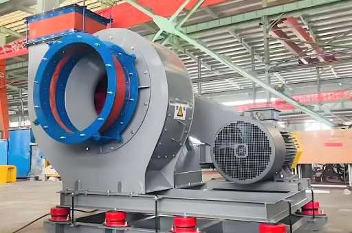
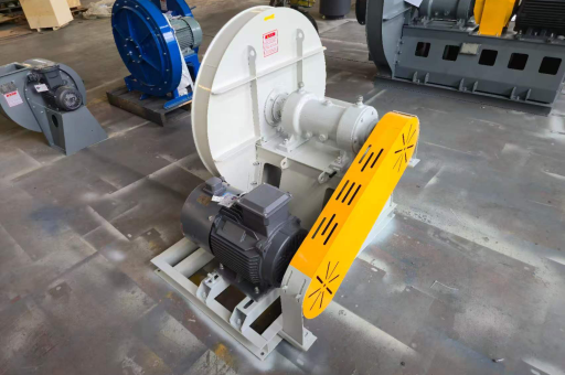
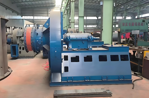
Core Design and Construction
Impeller and Housing Materials
The 9-19-16D typically features a backward-inclined blade design made from high-strength Q345B or 16Mn steel for corrosion resistance and structural integrity. Blade thickness ranges from 6 mm to 12 mm depending on operating temperature (standard: ≤250°C; high-temp option: ≤400°C with stainless steel). The housing is constructed from welded steel plate with a reinforced volute that reduces pressure losses at the fan outlet.
Drive System and Bearing Configuration
As a direct-drive (D) fan, the impeller is mounted on an extended motor shaft using a keyed or tapered bushing. This eliminates belt slip, reduces maintenance, and maintains constant speed vs. belt-driven types. Bearings are double-row spherical roller bearings (SKF or equivalent) with grease nipples for periodic lubrication. For high-temperature environments, synthetic grease is recommended to prevent thermal degradation.
Performance Characteristics
Pressure, Flow, and Efficiency Curves
Based on published test data from reputable fan manufacturers, the 9-19-16D achieves:
- Static pressure range: 10,000 Pa to 16,000 Pa (at 1450–1800 RPM).
- Airflow volume: 30,000 m³/h to 80,000 m³/h (varies with motor power).
- Peak efficiency: Approximately 78%–82% at the design point (BEP).
The performance curve is relatively steep, meaning small changes in system pressure produce significant flow changes—a characteristic best suited for stable duct systems with minimal variation.
Noise and Vibration Control
Due to high tip speeds (up to 120 m/s), noise levels can reach 85–92 dB(A) at full load. Standard mitigation includes:
- Inlet sound attenuators (silencers).
- Flexible connectors at inlet/outlet.
- Vibration isolators (spring or rubber) under the base frame.
Vibration severity per ISO 14694 should target <4.5 mm/s RMS at the bearing housings.
Common Industrial Applications
Boiler Forced Draft and Induced Draft
In coal-fired or biomass boilers, the 9-19-16D supplies combustion air (forced draft) or removes flue gases (induced draft). Its high static pressure overcomes economizer, air preheater, and duct friction losses. Key requirement: corrosion-resistant coating if sulfur content is high.
Pneumatic Conveying and Dust Collection
For conveying cement, fly ash, or wood chips, the fan generates the negative pressure needed to transport bulk materials through pipelines. In baghouse dust collectors, it maintains ΔP across filter bags, ensuring constant suction at the hoods.
Installation Best Practices
Foundation, Alignment, and Ductwork
Before installing the 9-19-16D fan:
- Foundation: Pour a reinforced concrete base at least 300 mm thick; allow 7 days for curing.
- Alignment: Use a laser alignment tool to ensure motor shaft and impeller hub concentricity ≤0.05 mm TIR.
- Ductwork: Keep inlet/outlet straight duct lengths to ≥3× duct diameter to avoid turbulence and performance degradation.
Inlet and Outlet Connections
- Inlet: Install an inlet box (or bell mouth) to reduce vortex formation.
- Outlet: A transition piece (rectangular to round or vice versa) should have a divergence angle <15° to prevent separation.
Maintenance and Troubleshooting
Bearing Lubrication and Replacement
- Grease type: Lithium-based or synthetic (e.g., Mobilith SHC 100).
- Frequency: Every 3 months (normal) or monthly (high temperature).
- Bearing life: Typically 25,000–40,000 hours under proper alignment.
Warning: Over-greasing can cause overheating; inject only until fresh grease appears at the relief valve.
Impeller Balancing and Wear Inspection
- Balance grade: G6.3 per ISO 1940 is standard; G2.5 for critical installations.
- Wear points: Leading edge of blades, near inlet cone and scroll cut-off.
- Corrective action: Weld build-up with hard-facing alloy (e.g., Stellite) or replace impeller when thickness has reduced by 30%.
Frequently Asked Questions (FAQ)
Q: What is the maximum operating temperature for a 9-19-16D fan?
A: Standard version: 250°C continuous. For temperatures up to 400°C, specify a hot-air version with stainless steel impeller (SS304 or SS316L) and high-temperature bearings.
Q: Can I use a 9-19-16D fan for suction (vacuum) service?
A: Yes—the design is symmetrical enough for both pressure and vacuum applications, but ensure the housing gasket and shaft seal are rated for negative pressure (e.g., lip seal or labyrinth seal).
Q: How do I calculate the required motor power?
A: Use the formula:
P (kW) = (Flow m³/s × Total Pressure Pa) / (1000 × η)
where η is fan efficiency (e.g., 0.80). Add 10–15% margin for startup and system uncertainty.
Q: Why is my fan vibrating after startup?
A: Common causes:
- Unbalanced impeller due to uneven wear or dust buildup.
- Misaligned motor and fan shaft.
- Resonance with foundation (check bolt tightness).
- Worn bearings (listen for grinding noise).
Start troubleshooting by checking balance and alignment before replacing parts.
Q: What is the difference between a 9-19 and a 9-26 series fan?
A: The 9-26 series has a smaller impeller diameter for the same flow but runs at higher RPM. The 9-19 series provides higher static pressure at a given flow due to increased blade depth. Choose based on your system resistance vs. space height constraints.
Conclusion: How to Select the Right Fan for Your System
Choosing the 9-19-16D high-pressure centrifugal fan requires careful analysis of system resistance, temperature, and duty cycle. Start by measuring the system’s static pressure drop (using a manometer or CFD simulation) and expected airflow. Then cross-reference the fan’s performance curve to operate within the 80–100% capacity range for best efficiency.
Remember these success factors:
- Always install on an adequate foundation.
- Conduct at least one vibration survey during commissioning.
- Schedule quarterly bearing inspections and impeller visual checks.
In summary, the 9-19-16D is a robust, high-efficiency fan that, when correctly selected and maintained, delivers years of dependable service in harsh industrial environments. For custom applications—such as corrosive gas or explosive atmospheres (ATEX)—consult specialized fan manufacturers to ensure compliance with safety and performance standards.
This guide is based on compiled industry knowledge and manufacturer literature. All trademarked or branded product names mentioned are for reference only; no endorsement is implied.