This article's table of contents introduction:

- Table of Contents
- 1. Introduction to Pneumatic Conveying and the Need for High-Pressure Fans
- 2. How High-Pressure Fans Function in Pneumatic Conveying Systems
- 3. Key Technical Specifications of High-Pressure Fans for Conveying
- 4. System Design Considerations: Pressure, Velocity, and Material Properties
- 5. Performance Optimization and Energy Efficiency Strategies
- 6. Common Failure Modes and Maintenance Best Practices
- 7. Industry Applications: From Cement to Food Processing
- 8. Frequently Asked Questions (FAQ)
- 9. Conclusion: Selecting the Right High-Pressure Fan for Your System
** The Critical Role of High-Pressure Fans in Pneumatic Conveying Systems: Engineering Principles, Performance Optimization, and Industry Applications
Table of Contents
- Introduction to Pneumatic Conveying and the Need for High-Pressure Fans
- How High-Pressure Fans Function in Pneumatic Conveying Systems
- Key Technical Specifications of High-Pressure Fans for Conveying
- System Design Considerations: Pressure, Velocity, and Material Properties
- Performance Optimization and Energy Efficiency Strategies
- Common Failure Modes and Maintenance Best Practices
- Industry Applications: From Cement to Food Processing
- Frequently Asked Questions (FAQ)
- Conclusion: Selecting the Right High-Pressure Fan for Your System
Introduction to Pneumatic Conveying and the Need for High-Pressure Fans
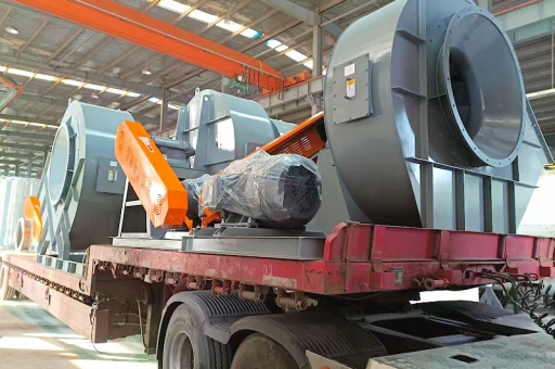
Pneumatic conveying is a material handling method that uses air or gas flow to transport bulk solids through pipes. It is widely adopted in industries such as cement, power generation, food processing, pharmaceuticals, and mining. The core component that drives these systems is the high-pressure fan. Unlike standard fans, high-pressure fans are designed to overcome significant system resistance caused by long pipe runs, numerous bends, and dense material loads.
In a typical dilute-phase pneumatic conveying system, the fan must generate pressures ranging from 0.3 to 1.5 bar (4.4 to 21.8 psi) to maintain velocities of 15 to 30 m/s. For dense-phase systems, pressures can exceed 3 bar. Without a properly selected high-pressure fan, the system will suffer from blockages, material degradation, and excessive energy consumption.
The global market for pneumatic conveying equipment is projected to exceed $35 billion by 2030, with high-pressure fans representing a critical sub-component for system reliability and efficiency.
How High-Pressure Fans Function in Pneumatic Conveying Systems
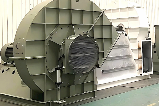
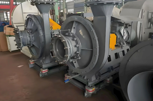
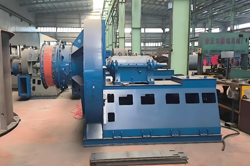
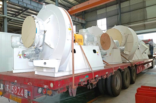
A high-pressure fan in a pneumatic conveying system serves as the prime mover of air. It creates the pressure differential required to push or pull material through the conveying line. These fans are typically centrifugal type, where air enters the impeller axially and is expelled radially at high velocity.
Key functional principles include:
- Pressure generation: The fan converts mechanical energy into kinetic energy (velocity) and then into static pressure. This static pressure is what pushes material through the pipe.
- Flow control: Variable frequency drives (VFDs) or inlet guide vanes adjust the airflow to match material feed rates.
- System integration: The fan is connected to a rotary valve or venturi pickup point where material enters the airstream.
In positive-pressure systems, the fan is placed at the beginning of the line, blowing material from a single source to multiple destinations. In negative-pressure (vacuum) systems, the fan is placed at the end, pulling material from multiple sources to a single collection point.
Key Technical Specifications of High-Pressure Fans for Conveying
When specifying a high-pressure fan for pneumatic conveying, several technical parameters must be evaluated:
| Specification | Description | Typical Range |
|---|---|---|
| Static Pressure | Resistance the fan must overcome | 3 - 3.0 bar |
| Airflow Rate | Volume of air per unit time | 100 - 10,000 m³/h |
| Impeller Diameter | Directly affects pressure and flow | 200 - 1500 mm |
| Motor Power | Drives the impeller | 5 - 500 kW |
| Material of Construction | Affects durability and corrosion resistance | Carbon steel, stainless steel, aluminum |
| Speed (RPM) | Determines pressure rise | 1500 - 6000 RPM |
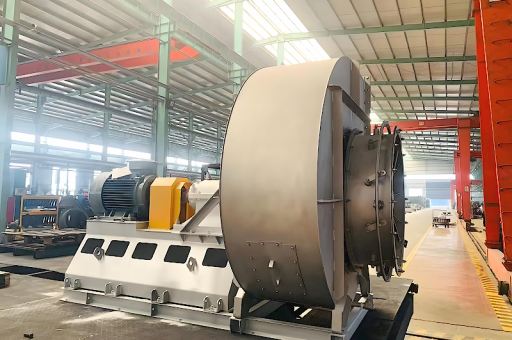
Critical note: For abrasive materials like sand or cement, the impeller should be coated with hard-face alloys or made from high-chrome cast iron to extend service life.
System Design Considerations: Pressure, Velocity, and Material Properties
Designing a pneumatic conveying system around a high-pressure fan requires balancing three variables: pressure, velocity, and material characteristics.
- Minimum conveying velocity: Each material has a saltation velocity – the speed at which particles begin to drop out of suspension. Below this speed, blockages occur. For example, fly ash requires at least 15 m/s, while plastic pellets can be conveyed at 10 m/s.
- Pressure drop calculation: The fan must compensate for pressure losses in straight pipes, bends, valves, and the pickup point. A typical pressure drop in a 100-meter horizontal line with four 90° bends is about 0.5 bar.
- Material density and particle size: Dense, coarse materials require higher pressures but lower velocities. Fine, light materials can be conveyed at higher velocities but lower pressures.
Common mistakes in system design:
- Oversizing the fan, leading to excessive velocity and material degradation.
- Undersizing the fan, causing frequent blockages.
- Ignoring air leakage at rotary valves, which reduces effective conveying pressure.
Performance Optimization and Energy Efficiency Strategies
Pneumatic conveying systems are often energy-intensive, with fans consuming up to 60% of total plant energy. Optimizing the high-pressure fan can yield significant cost savings.
Energy-saving strategies include:
- Variable frequency drives (VFDs): Matching fan speed to actual demand reduces energy consumption by 20–40% compared to fixed-speed operation.
- Inlet guide vanes: Adjusting the air intake angle reduces pressure drop while maintaining efficiency.
- Proper pipe sizing: Larger diameter pipes reduce velocity and friction losses, allowing the fan to run at lower pressure.
- Leak detection and sealing: Even small leaks in the conveying line can cause a 10–15% drop in efficiency.
- Scheduled impeller cleaning: Dust buildup on blades disrupts aerodynamic performance.
Case study: A cement plant replaced a fixed-speed high-pressure fan with a VFD-equipped model and saw energy savings of 32%, translating to $45,000 per year in electricity costs.
Common Failure Modes and Maintenance Best Practices
High-pressure fans in pneumatic conveying experience significant wear and stress. Common failure modes include:
| Failure Mode | Root Cause | Prevention |
|---|---|---|
| Impeller erosion | Abrasive material impact | Hard-facing, wear liners, periodic inspection |
| Bearing failure | Overload, misalignment, or contamination | Regular greasing, alignment checks, sealing upgrades |
| Vibration | Unbalanced impeller, loose mounting | Dynamic balancing, bolt tightening, foundation checks |
| Motor overheating | Overloading or poor ventilation | VFD adjustment, cooling fan inspection |
| Noise increase | Air turbulence or mechanical looseness | Acoustic enclosures, dampers, secure fasteners |
Preventive maintenance schedule:
- Weekly: Check vibration levels, bearing temperature, and airflow.
- Monthly: Clean impeller blades and inspect for wear.
- Quarterly: Replace filters, lubricate bearings, and verify drive alignment.
- Annually: Complete fan overhaul, balance rotor, and replace seals.
Industry Applications: From Cement to Food Processing
High-pressure fans are used across diverse industries for pneumatic conveying:
- Cement and minerals: Transport of raw meal, clinker, and fly ash over long distances. Fans must handle temperatures up to 150°C and abrasive dust.
- Food and grain: Conveying flour, sugar, starch, and grains. Sanitary designs with stainless steel and easy-clean surfaces are required.
- Pharmaceuticals: Powders and granules must be conveyed without contamination or degradation. Explosion-proof fans are often mandatory.
- Plastics and chemicals: Conveying plastic pellets, resins, and chemical powders. Fans must be corrosion-resistant for aggressive chemical environments.
- Power generation: Transport of pulverized coal and biomass to boilers. High reliability and redundancy are critical.
Emerging trend: The integration of wind turbine technology for remote or off-grid pneumatic conveying operations. Some facilities are exploring wind-powered fans for low-speed, continuous conveying in remote mineral extraction sites.
Frequently Asked Questions (FAQ)
Q1: What is the difference between a standard fan and a high-pressure fan for pneumatic conveying?
A: A standard fan typically generates less than 0.1 bar of static pressure, while a high-pressure fan can produce 0.3 bar to 3 bar. High-pressure fans also have stronger impellers, heavier bearings, and are designed for continuous duty.
Q2: How do I calculate the required static pressure for my pneumatic conveying system?
A: You need to sum the pressure drops across all piping components, including straight sections (using Darcy-Weisbach or empirical formulas), elbows, valves, and the material pickup point. Add a safety factor of 10–15%.
Q3: Can I use a high-pressure fan for both dilute-phase and dense-phase conveying?
A: Dilute-phase systems typically need lower pressure (0.3–0.7 bar) and high velocity. Dense-phase systems require higher pressure (1–3 bar) but lower velocity. Some fans are designed for both by using VFD and pressure control, but dedicated designs are more efficient.
Q4: How often should I replace the impeller?
A: Depending on material abrasiveness, impeller life can range from 6 months (cement or sand) to 5 years (plastic pellets). Regular inspection for pitting and erosion is essential.
Q5: What energy savings can I expect from using a VFD with my high-pressure fan?
A: In a variable-load pneumatic conveying system, a VFD reduces energy consumption by 20–40%. Payback periods are typically 1–2 years.
Q6: Is it feasible to use renewable energy to power a high-pressure fan in pneumatic conveying?
A: Yes, especially in remote applications. For example, a wind turbine can be coupled with a high-pressure fan to power a pneumatic conveying system for bulk material loading in off-grid locations. This reduces reliance on diesel generators.
Conclusion: Selecting the Right High-Pressure Fan for Your System
The high-pressure fan is the heart of any pneumatic conveying system. Selecting the wrong fan leads to system failures, high energy bills, and material loss. By understanding the principles of pressure generation, material properties, and system design, you can choose a fan that delivers reliable, efficient performance.
Key takeaways:
- Match fan pressure and flow to your system’s specific resistance and material characteristics.
- Invest in VFDs and proper pipe sizing for energy efficiency.
- Implement a rigorous maintenance program to extend fan life.
- Consider renewable energy integration, such as a wind turbine, for sustainable operations in remote locations.
With the right high-pressure fan, your pneumatic conveying system will operate smoothly, maintain consistent throughput, and minimize operational costs.
Final Recommendations:
Consult with fan manufacturers and system integrators to perform a detailed pressure drop calculation before purchasing. Request performance curves at your operating point and validate them with field measurements. Regularly monitor vibration, temperature, and flow to catch issues early. For sustainable operations, evaluate hybrid energy solutions, including a wind turbine as a supplementary or primary power source for your high-pressure fan.