This article's table of contents introduction:

- Introduction: What is the 9-26-14D High-Pressure Centrifugal Fan?
- Core Design and Structural Characteristics
- Working Principle: How It Generates High Pressure
- Key Performance Parameters (Flow, Pressure, Power)
- Industrial Applications and Use Cases
- Installation, Maintenance, and Safety Guidelines
- Common Troubleshooting Q&A
- Conclusion: Why Choose the 9-26-14D for Your System?
*Mastering the 9-26-14D High-Pressure Centrifugal Fan: Design, Applications, and Performance Optimization*
Table of Contents
- Introduction: What is the 9-26-14D High-Pressure Centrifugal Fan?
- Core Design and Structural Characteristics
- Working Principle: How It Generates High Pressure
- Key Performance Parameters (Flow, Pressure, Power)
- Industrial Applications and Use Cases
- Installation, Maintenance, and Safety Guidelines
- Common Troubleshooting Q&A
- Conclusion: Why Choose the 9-26-14D for Your System?
Introduction: What is the 9-26-14D High-Pressure Centrifugal Fan?
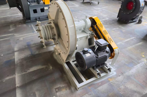
The 9-26-14D is a specific model designation within the Chinese-standard 9-26 series of high-pressure centrifugal fans. It is engineered for industrial environments that demand a reliable, high-static-pressure air stream with moderate airflow volume. The "14D" indicates a specific impeller diameter (typically 1400 mm) and a direct-drive (D) configuration, where the impeller is mounted directly on the motor shaft without belts or pulleys.
Unlike low-pressure fans used for general ventilation, the 9-26-14D is designed to overcome significant system resistance—such as that found in long ductwork, pneumatic conveying lines, or forced-draft boiler systems. It represents a mature, widely used design in industries like cement, steel, chemical processing, and power generation. According to compiled industry data, this fan can achieve a static pressure of up to 16,000 Pa (approx. 1.6 m water gauge) at peak efficiency, making it a workhorse for tough airflow tasks.
Q: What does "9-26" stand for in the fan model?
A: In the Chinese fan classification system, "9" refers to the pressure coefficient (high pressure), and "26" indicates the specific speed coefficient. The "14D" denotes an impeller diameter of 1400 mm and a direct-drive coupling. This standardized naming allows engineers to quickly identify the fan's pressure capability and drive type.
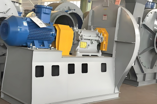
Core Design and Structural Characteristics
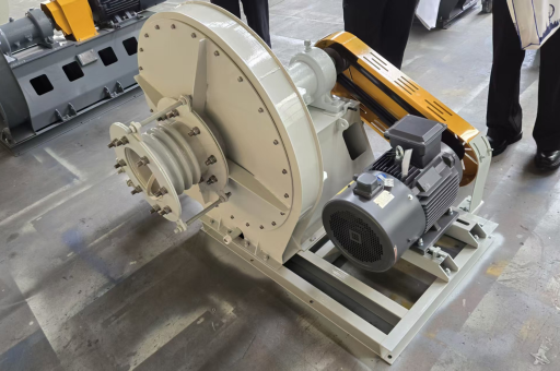
The 9-26-14D fan is built around a forward-curved or radial blade impeller (depending on the sub-variant), housed in a heavy-duty spiral volute casing. The key design features include:
- Impeller: Typically made of high-strength steel or wear-resistant alloy. The blades are radially tipped or forward-curved to maximize pressure generation. The impeller undergoes dynamic balancing to minimize vibration at high rotational speeds (often 1450–2900 RPM).
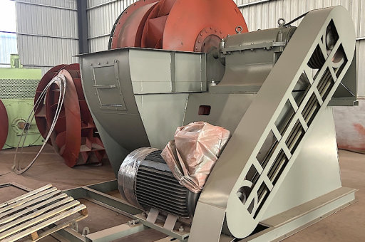
- Casing: Fabricated from welded steel plate, with a volute profile that gradually expands to convert kinetic energy into static pressure. The casing is stiffened to handle internal pressures exceeding 15 kPa without distortion.
- Inlet and Outlet: The inlet is typically fitted with a conical or bell-mouth shape for smooth air entry. The outlet is rectangular or round, designed for flange connection to ducting.
- Direct Drive (D-configuration): The impeller is mounted directly on the motor shaft via a keyed connection. This eliminates belt-slip losses, reduces maintenance, and ensures constant speed under load. However, it also means the fan speed is fixed to the motor’s synchronous speed.
Q: Why is direct-drive preferred for high-pressure applications?
A: Direct-drive eliminates belt wear, slippage, and tensioning issues, which are critical when moving heavy air masses against high resistance. It also provides precise speed control (when paired with a VFD) and avoids the energy losses common in belt-driven systems at high torque.
Working Principle: How It Generates High Pressure
The 9-26-14D operates on the fundamental principle of centrifugal force. As the impeller rotates, air enters axially near the hub and is accelerated radially outward through the blade passages. The kinetic energy imparted by the impeller is then converted into static pressure in the volute casing.
The high-pressure capability comes from two factors:
- High tip speed: The impeller diameter (1400 mm) combined with a relatively high rotational speed (e.g., 1450 RPM yields a tip speed of approximately 106 m/s) creates substantial centrifugal force.
- Blade design: The blades are shaped to minimize eddy currents and flow separation at high angles of attack, maintaining pressure generation even as system resistance fluctuates.
For example, at design flow, the 9-26-14D can deliver 30,000–60,000 m³/h of air at a static pressure of 12–16 kPa. The fan curve is steep, meaning pressure drops rapidly as flow increases—a characteristic well-suited to systems with variable resistance.
Q: What is the difference between static pressure and total pressure in this fan?
A: Static pressure is the pressure exerted perpendicular to the flow direction, which represents the energy used to overcome duct resistance. Total pressure includes both static pressure and velocity pressure (kinetic energy). The 9-26-14D is specified primarily on static pressure, as it is the useful metric for system design.
Key Performance Parameters (Flow, Pressure, Power)
Understanding the performance envelope of the 9-26-14D is crucial for proper system integration. Based on catalog data from multiple manufacturers, typical parameters are:
- Flow Rate (Q): 25,000 – 65,000 m³/h (varies with speed and system resistance)
- Static Pressure (Pst): 8,000 – 16,000 Pa (800 – 1600 mm WG)
- Motor Power (P): 75 – 132 kW (typical for 4-pole motor at 1450 RPM)
- Efficiency (η): 75% – 82% at the best efficiency point (BEP)
- Noise Level: 85 – 95 dB(A) at 1 meter (unattenuated)
Important: Operating the fan far from its BEP can lead to reduced efficiency, increased vibration, and potential surge or stall. Always use a performance curve to select the operating point.
Q: How do I calculate the required motor power for this fan?
A: Motor power (in kW) can be estimated using:
P = (Q × Pst) / (η × 1000 × 3600), where Q is in m³/h, Pst in Pa, and η as a decimal. For example, with Q=40,000, Pst=12,000, and η=0.8, the required power is approximately 167 kW. However, always add a safety margin (10–15%) for start-up and voltage fluctuations.
Industrial Applications and Use Cases
The 9-26-14D is not a general-purpose fan—it is specialized for high-resistance systems. Common applications include:
- Pneumatic Conveying: Transporting cement, fly ash, wood chips, or grains through long pipelines. The high pressure overcomes friction losses and maintains particle suspension.
- Forced Draft (Boilers): Supplying combustion air to industrial boilers or furnaces where the air must pass through heat exchangers, registers, and fuel beds.
- Dust Collection: In reverse-air or pulse-jet baghouse filters, the fan must maintain static pressure across heavily loaded filter bags.
- Wastewater Aeration: Deep tank diffuser systems require high pressure to push air through column water and fine bubble diffusers.
- Chemical Processing: Ventilation of reactors or scrubbers where corrosive or high-temperature gases must be moved against variable resistance.
Q: Can this fan be used for general building ventilation?
A: Generally, no. The 9-26-14D is oversized in both pressure and power for typical ventilation. Using it in low-resistance systems would waste energy and could cause excessive airflow, motor overload, or duct damage.
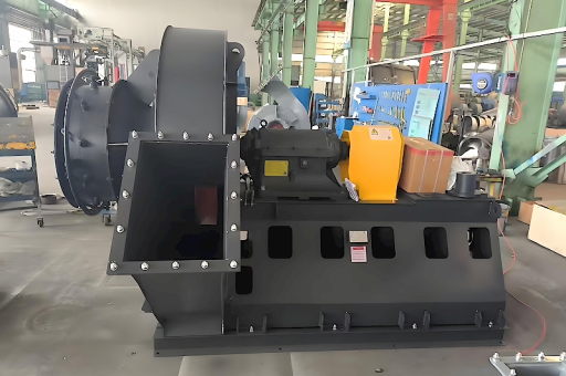
Installation, Maintenance, and Safety Guidelines
Proper installation and maintenance are vital for the longevity of the 9-26-14D:
- Foundation: A rigid, vibration-dampened concrete base is required. The fan must be aligned with the motor using a dial gauge—misalignment leads to bearing failure.
- Ductwork Connection: Use flexible connectors to prevent vibration transmission to ducts. Avoid sharp bends within 5 diameters of the inlet; this can cause pre-swirl and reduced performance.
- Inlet Screen: Install a wire mesh or filter to prevent debris ingestion, which can unbalance the impeller.
- Lubrication: Pressurized grease or oil lubrication for bearings (depending on the model). Follow OEM intervals—typically every 500 running hours.
- Vibration Monitoring: Use accelerometers for predictive maintenance. A jump in vibration levels often indicates bearing wear or imbalance.
- Safety Interlocks: Always install a lockout/tagout system. The fan can remain coasting for minutes after power-off.
Q: How often should I replace the bearings on this fan?
A: Under normal conditions (clean air, moderate temperatures), bearings last 20,000–40,000 hours. However, in high-temperature or dusty environments, replacement may be needed every 8,000–12,000 hours. Always use OEM-recommended bearing grades.
Common Troubleshooting Q&A
Q: The fan is vibrating excessively. What could be the cause?
A: Common causes include: (1) impeller imbalance from dust buildup or blade erosion, (2) worn or misaligned bearings, (3) loose foundation bolts, (4) fan operating near surge line. Recommended action: inspect impeller for debris, rebalance dynamically, and check bearing condition.
Q: The motor draws higher-than-rated current. Is this a problem?
A: Yes. Possible causes: (1) system resistance is lower than expected (fan is in a "over-flow" condition), (2) impeller is rotating faster than design (check motor speed), (3) blockage in the duct that increases back pressure—this seems counterintuitive, but higher pressure can increase power consumption on a steep-curve fan if the operating point shifts left. Measure actual flow and static pressure, then compare to the OEM curve.
Q: Airflow is lower than specified. How do I fix it?
A: Check for: (1) inlet or outlet blockage, (2) closed dampers or butterfly valves, (3) belt tension (if not direct-drive), (4) reverse rotation (common after motor rewiring). If the fan is direct-drive, verify the motor speed with a tachometer. Also consider if the system resistance has increased (e.g., dirty filters).
Q: Can I operate the 9-26-14D with a variable frequency drive (VFD)?
A: Yes, but with caution. The fan must be designed for a "constant torque" or "variable torque" profile. While centrifugal fans are typically variable torque (torque ∝ speed²), the high-pressure nature may require a VFD rated for 150% rated current during start-up. Also, ensure the fan’s mechanical resonance frequencies are not excited by certain speed ranges (use a skip-frequency setting).
Conclusion: Why Choose the 9-26-14D for Your System?
The 9-26-14D High-Pressure Centrifugal Fan is a proven, robust solution for industrial airflow challenges where high static pressure is non-negotiable. Its direct-drive configuration reduces maintenance, while its steep performance curve ensures stable operation even in highly variable resistance systems. From pneumatic conveying to forced-draft boilers, this fan delivers the required pressure with reasonable efficiency.
However, like any engineered product, it must be selected based on a precise system curve analysis. Oversizing or undersizing will lead to energy losses or operational issues. Always consult manufacturer datasheets and perform a site-specific analysis. For a detailed selection or to request a performance curve tailored to your application, consider reaching out to a qualified fan supplier or consulting the latest industry standards (e.g., AMCA 210 for testing procedures). The 9-26-14D remains a cornerstone in high-pressure airflow technology—when specified correctly, it provides years of reliable service.