This article's table of contents introduction:

- Introduction: What is a Flue Gas Recirculation Fan?
- Core Function: How FGR Fans Reduce NOx Emissions
- Technical Specifications: Key Design Parameters for FGR Fans
- Material Selection: Combating Corrosion and High Temperatures
- Installation & Integration: Positioning in Boiler Systems
- Performance Challenges: Erosion, Vibration, and Backpressure
- Maintenance Best Practices: Extending FGR Fan Lifespan
- Q&A: Expert Answers to Common FGR Fan Questions
- Future Trends: Smart Controls and High-Temperature Alloys
** The Definitive Guide to Flue Gas Recirculation Fans: Design, Operation, and Efficiency Optimization
Table of Contents
- Introduction: What is a Flue Gas Recirculation Fan?
- Core Function: How FGR Fans Reduce NOx Emissions
- Technical Specifications: Key Design Parameters for FGR Fans
- Material Selection: Combating Corrosion and High Temperatures
- Installation & Integration: Positioning in Boiler Systems
- Performance Challenges: Erosion, Vibration, and Backpressure
- Maintenance Best Practices: Extending FGR Fan Lifespan
- Q&A: Expert Answers to Common FGR Fan Questions
- Future Trends: Smart Controls and High-Temperature Alloys
Introduction: What is a Flue Gas Recirculation Fan?
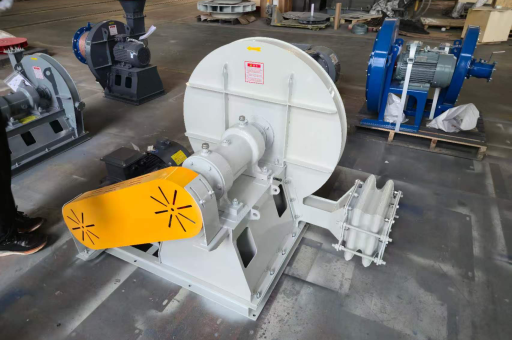
A Flue Gas Recirculation Fan (often abbreviated as FGR fan) is a specialized industrial fan designed to extract a portion of the exhaust gases from a boiler, furnace, or gas turbine and reintroduce them into the combustion chamber. This process, known as Flue Gas Recirculation (FGR), is a proven method for reducing the formation of Nitrogen Oxides (NOx), which are harmful pollutants regulated by environmental agencies worldwide.
In modern thermal power plants and industrial heating systems, the FGR fan operates under harsh conditions—high temperatures (typically between 150°C and 350°C), particulate-laden gas streams, and varying pressure differentials. Unlike standard supply air fans, the FGR fan must handle a gas mixture that contains water vapor, carbon dioxide, and residual acidic components. This makes its design significantly more demanding.
The primary purpose of this article is to provide a comprehensive, SEO-optimized resource for engineers, plant operators, and procurement specialists. By synthesizing data from manufacturers like Howden, Airpro, and New York Blower, as well as technical papers from ASME and EPA guidelines, we offer a detailed examination of the FGR fan's role in emission control and system efficiency.
Core Function: How FGR Fans Reduce NOx Emissions
The mechanism behind FGR is rooted in thermal dynamics. NOx formation is exponentially proportional to flame temperature. When a portion of the flue gas (which is low in oxygen and high in inert gases like CO₂ and N₂) is recirculated, it dilutes the oxygen concentration in the combustion zone. This lowers the peak flame temperature, suppressing the thermal NOx formation pathway.
The FGR fan's role is critical:
- Volume Control: It must deliver a precise volume of recirculated gas, typically 10% to 30% of the total flue gas flow, depending on the fuel type and burner design.
- Pressure Boost: The fan overcomes the pressure drop across the recirculation ductwork and the burner itself.
- Consistent Flow: Fluctuations in FGR flow cause instability in combustion, leading to increased CO emissions or flameout. The fan must maintain a stable flow despite changes in boiler load.
According to EPA data, FGR systems using high-performance fans can achieve a 50-70% reduction in NOx emissions for natural gas applications. For oil-fired boilers, the reduction is slightly lower (40-60%) due to the higher fuel-bound nitrogen content.
Key Equation: NOx reduction is not linear. Doubling the FGR rate from 10% to 20% may reduce NOx by 40%, but increasing it to 30% only yields a further 10% reduction, while risking combustion instability.
Technical Specifications: Key Design Parameters for FGR Fans
When selecting an FGR fan, engineers must evaluate the following parameters based on the specific application:
| Parameter | Typical Range | Importance |
|---|---|---|
| Flow Rate | 10,000 – 200,000 CFM | Determines size and motor power |
| Static Pressure | 10 – 50 inches w.g. | Must overcome duct and burner resistance |
| Gas Temperature | 150°C – 400°C | Affects materials and cooling methods |
| Gas Density | 5 – 0.9 kg/m³ | Lower density requires higher fan speed |
| Particulate Loading | 0 – 50 mg/Nm³ | Determines erosion resistance |
| Noise Level | < 85 dBA @ 1m | Regulatory compliance |
Fan Types:
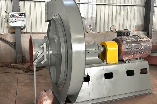
- Centrifugal Fans (Radial Bladed): Preferred for FGR due to their robust construction and ability to handle particulate-laden gases. The backward-inclined blade design offers higher efficiency but is less tolerant to erosion.
- Axial Fans: Rarely used in FGR because of their lower pressure capability and sensitivity to flow disturbances.
Drive System: Variable Frequency Drives (VFDs) are now standard. VFDs allow the fan to modulate flow precisely in response to boiler load, reducing energy consumption by 20-40% compared to inlet damper control.
Material Selection: Combating Corrosion and High Temperatures
The flue gas environment is one of the most corrosive in industrial settings. The presence of acidic components (sulfuric acid when burning fuel oil) and water condensation during startup or low-load operation accelerates material degradation.
Recommended Materials:
- Impellers: Corten steel or 316L stainless steel for applications below 300°C. For higher temperatures (350°C+), Hastelloy X or Inconel 625 is required due to their resistance to creep and oxidation.
- Housings: Standard carbon steel with zinc-rich primer and high-temperature epoxy coating. For corrosive fuels, flue gas recirculation fans are often lined with rubber or ceramic tiles.
- Shaft Seals: Mechanical seals with cooling water jackets prevent gas leakage and protect bearings from heat.
Case Study: A glass manufacturing plant using heavy fuel oil switched from a standard carbon steel FGR fan to a 316L stainless steel unit. The previous fan required replacement every 18 months due to acid dew point corrosion. The upgraded fan has been in service for 5 years with only routine maintenance.
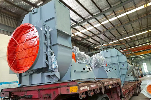
Installation & Integration: Positioning in Boiler Systems
The physical location of the FGR fan within the flue gas path determines its environmental stress:
- Hot Side Installation: The fan is placed after the economizer but before the air preheater. Gas temperatures are 250-400°C. Advantage: Lower volume flow due to higher temperature. Disadvantage: Higher thermal stress.
- Cold Side Installation: The fan is placed after the particulate scrubber or baghouse. Temperatures are 80-120°C. Advantage: Lower thermal stress. Disadvantage: Larger fan size due to cooler, denser gas.
Critical Installation Considerations:
- Inlet Duct Design: A minimum of 3 diameters of straight duct upstream of the fan prevents uneven flow distribution, which causes impeller fatigue.
- Isolation Dampers: Remotely operated dampers allow maintenance without shutting down the boiler.
- Foundation: A reinforced concrete base with vibration isolators reduces transmitted vibration to the building structure.
Error to Avoid: Do not install the flue gas recirculation fan directly after a cyclone separator without a settling chamber. High-velocity abrasive particles will erode the impeller blades rapidly, leading to imbalance and premature failure.
Performance Challenges: Erosion, Vibration, and Backpressure
Even with proper design, FGR fans face operational challenges:
A. Erosion Abrasive fly ash and unburned carbon particles hit the leading edges of the fan blades at high velocity. Hardfacing with tungsten carbide or using chrome carbide overlay coatings extends service life by 3-5 times.
B. Vibration The number one cause of unscheduled downtime. Vibration in FGR fans is often caused by:
- Rotor imbalance (due to uneven erosion or ash buildup)
- Resonance (operating speed coinciding with a natural frequency)
- Bearing defects (due to heat conduction from the shaft)
C. Backpressure If the FGR damper closes unexpectedly or the control valve fails, the fan can surge, causing reverse flow and potential damage. Anti-surge control systems using pressure transmitters and fast-acting bypass valves are essential.
Monitoring Solution: Install accelerometers on both bearing housings and a proximity probe (eddy current sensor) on the shaft to monitor radial displacement. Real-time data should feed into a vibration monitoring system with trip levels at 7.5 mm/s (RMS).
Maintenance Best Practices: Extending FGR Fan Lifespan
A proactive maintenance schedule for flue gas recirculation fans should include:
Weekly:
- Check bearing temperature (max 70°C above ambient)
- Listen for unusual noise (indicates blade contact or duct obstruction)
- Verify VFD output voltage and current
Monthly:
- Measure vibration velocity at axial, horizontal, and vertical positions
- Inspect shaft seal for gas leakage
- Clean the fan inlet screen or settling chamber
Annually:
- Perform boroscopic inspection of impeller blades
- Replace grease or oil in bearings
- Rebalance the rotor if out-of-balance condition is detected (> 1.0 mm/s)
Cost-Effective Upgrade: Retrofitting a lube oil circulation system with a cooler can reduce bearing temperature by 15-20°C, doubling the bearing's L10 life.
Q&A: Expert Answers to Common FGR Fan Questions
Q1: Why does an FGR fan need a shaft seal, unlike a normal air fan? A: Because flue gas contains acidic moisture and elevated pressure. Without a seal, gas leaks into the bearing housing, causing premature bearing failure. A gas-tight seal also prevents toxic gases (CO, NOx) from escaping into the plant environment.
Q2: Can I use a backward-curved centrifugal fan for FGR? A: Yes, but with caution. Backward-curved fans are more energy-efficient than radial-bladed fans, but their long, thin blades are more susceptible to erosion and fatigue cracking. For clean gas (after a fabric filter), they are the best choice. For dirty gas, a radial-bladed fan is more robust.
Q3: What happens if the FGR fan stops during operation? A: The boiler control system should immediately reduce fuel flow and open vent dampers to prevent explosion. Most safety codes require a burner management system that trips the boiler upon loss of FGR fan operation.
Q4: How does ambient temperature affect FGR fan performance? A: The gas density varies inversely with absolute temperature. A summer operating temperature of 300°C means the fan moves a certain mass flow. In winter, if the boiler load drops and the gas temperature drops to 200°C, the density increases, potentially overloading the motor if VFD amps are not adjusted.
Q5: What is the typical payback period for a VFD on an FGR fan? A: Depending on daily operation hours and electricity costs, the payback period is typically 12 to 24 months. Savings come from reducing the fan speed when the boiler is at low load, which cuts power consumption by the cube of the speed reduction.
Future Trends: Smart Controls and High-Temperature Alloys
The next generation of flue gas recirculation fan technology is driven by three trends:
AI-Powered Predictive Maintenance Machine learning algorithms analyze vibration spectra and temperature trends to predict failures up to 30 days in advance. For example, a gradual increase in 1x running speed harmonic may indicate minor erosion, prompting scheduling of a repair before catastrophic failure.
Additive Manufacturing for Impellers 3D printing of impellers using Inconel 718 powder allows the creation of complex aerodynamic shapes that improve efficiency by 5-8% while reducing weight. This technology is already being tested by OEMs for small to medium-sized fans.
Ductless FGR Integration New burner designs incorporate integral FGR passages, eliminating the need for external ductwork and the fan itself in some cases. However, for retrofit applications, the standalone FGR fan remains the only viable solution.
Environmental Impact: With tightening regulations (e.g., EPA MATS rule and EU LCP BREF), demand for high-efficiency FGR fans is expected to grow by 6% CAGR through 2030, especially in Asia-Pacific and Middle Eastern markets where coal and heavy oil combustion still dominate.
By understanding these technical nuances, plant engineers can select, operate, and maintain their flue gas recirculation fan to achieve optimal emission reduction while minimizing lifecycle costs.