This article's table of contents introduction:

- What is a 75kW Centrifugal Fan with VFD?
- The Critical Relationship: Affinity Laws
- Typical Specifications for a 75kW VFD Centrifugal Fan System
- Key Components of the System
- Advantages of VFD Control (vs. Other Methods)
- Key Installation & Operational Considerations
- Common Applications for a 75kW VFD Centrifugal Fan
- Summary Action Items if you are specifying or troubleshooting this system:
It sounds like you are referring to a 75 kW (approximately 100 HP) centrifugal fan powered by a Variable Frequency Drive (VFD) . This is a very common and powerful combination in heavy industrial applications (HVAC, mining, cement, power plants, or wastewater aeration).
Here is a comprehensive breakdown of what this system entails, its key characteristics, considerations, and typical specifications.
What is a 75kW Centrifugal Fan with VFD?
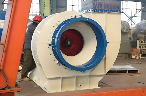
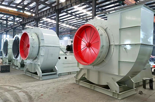
- Centrifugal Fan: Uses a rotating impeller to increase the velocity of air, creating pressure. It's ideal for high-pressure, medium-to-high flow applications against system resistance (ductwork, filters, scrubbers).
- Variable Frequency Drive (VFD): An electronic controller that varies the frequency (and voltage) supplied to the AC motor. For a centrifugal fan, this varies the fan's speed.
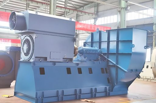
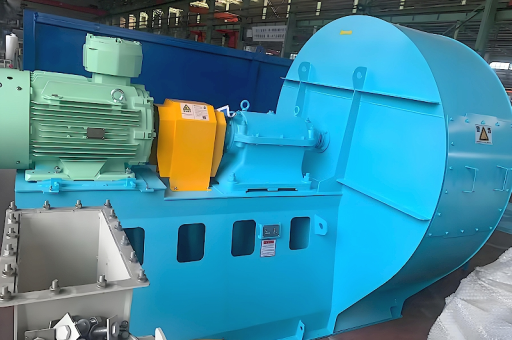
- 75 kW Motor: The prime mover. Typically a 3-phase induction motor (e.g., 400V, 415V, or 690V depending on region).
The Critical Relationship: Affinity Laws
The reason VFDs are so effective for centrifugal fans is due to the Fan Affinity Laws. When you change the fan speed (RPM), the following happens:
- Flow (CFM/m³/h) is proportional to Speed (RPM): $Q \propto N$
- Pressure (Static/Total) is proportional to Speed squared: $P \propto N^2$
- Power (kW) is proportional to Speed cubed: $P \propto N^3$
Why this matters for your 75kW system:
- If you reduce speed to 80% , power consumption drops to $0.8^3 = 0.51$ (51% of full load).
- At 80% speed, the 75kW fan would only draw approximately 38 kW.
- This cubic relationship results in HUGE energy savings (often 30-60%) compared to modulating inlet vanes or dampers.
Typical Specifications for a 75kW VFD Centrifugal Fan System
This is a large system. Example parameters:
| Parameter | Typical Value | Notes |
|---|---|---|
| Motor Power | 75 kW (100 HP) | FLA approx. 140A @ 400V / 80A @ 690V |
| Motor Voltage | 400V / 415V / 690V (3-phase) | Depends on region & cable length |
| VFD Rating | 75 kW (Varies) | Often oversized to 90-100kW to handle harmonics & peak starting torque. |
| Max Airflow | 40,000 - 80,000 m³/h | Depends on fan design & pressure |
| Max Static Pressure | 2,000 - 5,000 Pa | High pressure for industrial duct networks |
| Max Speed | 1,000 - 1,500 RPM | Speed is determined by fan diameter & motor poles |
| Fan Type | Backward Curved (BIC) or Airfoil | Most efficient for VFD control |
| Connection | Belt-driven or Direct Drive | Belt-driven offers mechanical torque adjustment; Direct Drive is more efficient. |
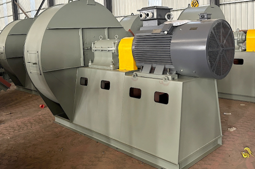
Key Components of the System
-
The VFD (Variable Frequency Drive):
- Function: Converts AC line power to DC, then synthesizes a variable-frequency AC output.
- Critical Features: DC choke (for harmonics reduction), braking chopper (if stopping quickly), PID controller (for precise duct pressure), fieldbus communication (Modbus, Profibus, Ethernet/IP).
- Brands: ABB, Siemens, Danfoss, Schneider, Yaskawa, Rockwell.
-
The Motor:
- Type: NEMA or IEC standard squirrel-cage induction motor.
- Rating: 75 kW, IP55 (for dusty environments), IC411 (self-cooled) or IC416 (forced cooling fan - essential for low-speed operation).
- Issue: The standard motor's self-cooling fan is inefficient at low speeds. A forced (independent) cooling fan is highly recommended if the fan will run below 30-40% speed for extended periods.
-
The Fan & Controls:
- Centrifugal Impeller: Backward-curved or airfoil blades are most efficient.
- Ductwork: Designed for the pressure drop.
- Sensors: Differential pressure transmitters (to control duct pressure), temperature sensors (motor & bearings), vibration sensors.
Advantages of VFD Control (vs. Other Methods)
- Energy Savings (Primary Benefit): As shown by the affinity laws, VFD control is the most efficient method of flow control (vs. dampers, inlet vanes, or outlet valves).
- Soft Start: The VFD ramps the motor up gradually (e.g., 30 seconds), eliminating the high inrush current (6-8x FLA) of direct-on-line (DOL) starting. This reduces mechanical stress on belts, bearings, and ductwork.
- Precise Process Control: The VFD can use a PID loop to maintain a specific duct pressure or airflow, regardless of changing filter conditions or damper positions.
- Reduced Noise: At lower speeds, the fan runs quieter.
- Extended Equipment Life: Less mechanical shock and lower operating speeds reduce wear on bearings, seals, and motor windings.
Key Installation & Operational Considerations
| Issue | Why it matters | Solution |
|---|---|---|
| Harmonics | A 75kW VFD is a large non-linear load, causing harmonics that can overheat transformers and nuisance trip other equipment. | Install a 3% or 5% DC link choke (often built-in) or a line reactor. For large installations, consider a 12-pulse or active front-end VFD. |
| Cable Length | Long motor cables (>30m) can cause voltage spikes at the motor terminals due to reflected waves, damaging insulation. | Use VFD-rated cable (triple-shielded) and install a dv/dt filter or sine-wave filter at the VFD output. |
| Motor Cooling | At low speeds (<30%), the motor's internal fan provides insufficient cooling, leading to overheating. | Specify a separate, externally-powered cooling fan for the motor (IC416). Or operate with a minimum speed limit. |
| Bearing Currents | VFD switching (PWM) can induce currents through the motor bearings, causing pitting and failure. | Use insulated bearings (N-end), shaft grounding rings, or a common-mode choke. |
| Braking | Does the fan need to stop quickly? A large fan has huge inertia. | If stopping quickly is needed, use a braking resistor and a braking chopper. Otherwise, let it coast to a stop. |
| Resonance / Critical Speeds | The fan has natural mechanical frequencies. The VFD might speed up the fan through a speed that causes violent vibration. | Program "skip frequencies" (speed bands) in the VFD to avoid operating at resonant speeds. |
| Inertia / Start Time | A large fan + ductwork takes a long time to spin up. The VFD must be sized for this. | Ensure the VFD has a "heavy duty" rating (often 110% or 120% overload for 60 seconds). |
Common Applications for a 75kW VFD Centrifugal Fan
- Cement Plants: Kiln ID fan, baghouse fan, raw mill fan.
- Mining: Underground ventilation (main fans), dust collection.
- Power Generation: Forced draft (FD) fan, Induced draft (ID) fan, Primary air (PA) fan, SCR flue gas desulfurization.
- Wastewater Treatment: Aeration blowers for activated sludge (though blowers are more common for pure air, centrifugal fans are used in some aeration systems).
- Large Commercial HVAC: Central plant air handlers for airports, stadiums, hospitals (supply/exhaust).
- Pharmaceuticals & Chemical: Clean room supply, fume exhaust, dust collection.
Summary Action Items if you are specifying or troubleshooting this system:
- Confirm Motor Cooling: Is it IP23 (self-cooled) or IP55 with a forced cooling fan? For variable speed, a forced fan is highly recommended if running below 40% speed.
- Check VFD Overload Rating: Is it rated for "Heavy Duty" (e.g., 110% overload for 60s) to handle fan starting surge?
- Check Harmonic Compliance: Does your facility require IEEE 519 compliance? You may need a line reactor or active filter.
- Verify Skip Frequencies: Ensure the VFD is programmed to skip any speeds where the fan/duct system vibrates.
- Protections: Install vibration transducers and temperature probes (motor bearings, motor windings) as a minimum.
If you have a specific question (e.g., "How do I size the cables?" or "Why is my VFD tripping on overcurrent?") feel free to ask