This article's table of contents introduction:

- Key Specifications Analysis
- "High-Efficiency" Context
- Typical Industrial Applications
- Impeller Diameter vs. Performance
- Critical Selection Considerations
- Summary Table
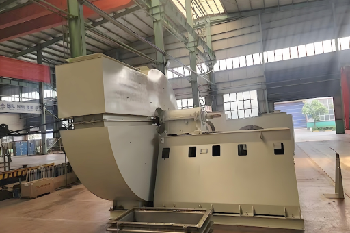
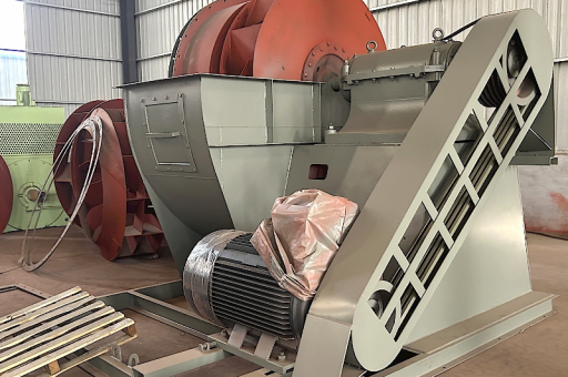
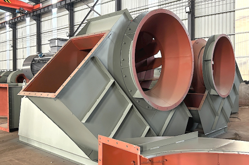
This is a technical specification for a large-scale, high-efficiency industrial centrifugal fan. Below is a breakdown of its key characteristics, typical applications, and design considerations based on the parameters you provided.
Key Specifications Analysis
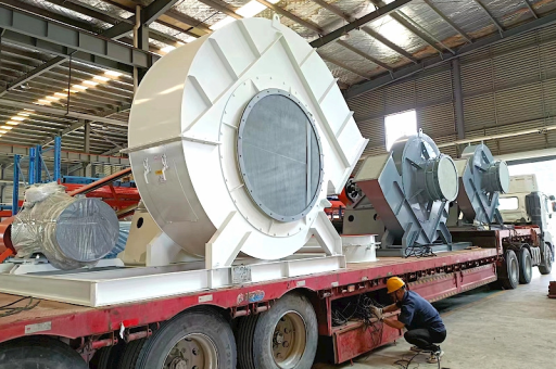
- Impeller Diameter: 800 – 2950 mm (31.5” – 116”)
- Implication: This is a very large fan range. The 2950mm impeller is massive, typically used in heavy industries. These are not standard HVAC fans; they are industrial process fans.
- Flow Rate (Volume): 15229 – 810,000 m³/h (≈ 8,960 – 476,000 CFM)
- Implication: This is an extremely high volume range. The upper limit (810,000 m³/h) is characteristic of main ventilation fans for mines, large power plant boilers, or massive wind tunnels.
- Pressure: 553 – 7218 Pa (≈ 2.2 – 29 inches w.g.)
- Implication: This is a medium to medium-high pressure range (in fan terms). It is suitable for overcoming the resistance of ductwork, filters, scrubbers, and heat exchangers, but is not a high-pressure compressor (e.g., for pneumatic conveying of dense materials at >15,000 Pa).
"High-Efficiency" Context
For this class of fan, "High-Efficiency" typically means achieving a peak static efficiency of 82% to 88% or higher, using advanced airfoil blades.
- Methods used to achieve this:
- Backward-Curved or Airfoil Blades: These are far more efficient than forward-curved or radial blades at high volumes and medium pressures.
- Computational Fluid Dynamics (CFD) Optimized: The housing and inlet cone are designed to minimize turbulence and recirculation.
- Variable Speed Control: To match actual system demand without throttle losses.
Typical Industrial Applications
Given the size, volume, and pressure, this fan is used in heavy process industries:
- Power Generation:
- Induced Draft (ID) fans for pulling exhaust through a boiler.
- Forced Draft (FD) fans for pushing combustion air into a boiler.
- Primary Air (PA) fans for coal mills.
- Cement Industry:
- Kiln exhaust fans.
- Raw mill and coal mill fans.
- Cooler exhaust fans (requiring high temperature resistance).
- Mining & Tunneling:
- Main mine ventilation fans (often used as axial fans, but large centrifugal fans are used for specific inline applications or auxiliary systems).
- Tunnel ventilation for subways or road tunnels.
- Steel & Metallurgy:
- Sintering plant fans.
- Converter gas recovery fans.
- Air supply for blast furnaces.
- Wastewater Treatment:
Large aeration blowers (using high-volume, medium-pressure centrifugal fans).
- Process Air:
- Large-scale dust collection systems (baghouses or electrostatic precipitators).
- Drying systems in paper, textile, or food processing.
Impeller Diameter vs. Performance
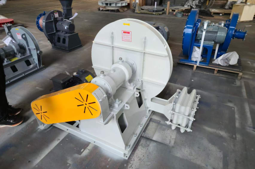
- 800mm Impeller: Handles the lower end of the flow (15,000 – 80,000 m³/h) and higher pressures (up to 7,000 Pa). Used for smaller process lines or medium-sized baghouses.
- 2950mm Impeller: Handles the upper end of the flow (400,000 – 810,000 m³/h) but at relatively lower pressures (near 500-1500 Pa). Used for massive ventilation systems or where pressure drop is low but volume is huge.
Critical Selection Considerations
If you are selecting this fan, you must verify the following:
- Air/Gas Properties:
- Temperature: Is it ambient (20°C)/normal temperature? Or hot (200°C – 400°C+) for boilers/kilns? High temperature requires different shaft seals, bearings, and impeller materials (e.g., Corten or stainless steel).
- Corrosion: Is the gas acidic (e.g., flue gas with SOx)? Requires corrosion-resistant coatings or alloys (316L, Duplex, etc.).
- Abrasion: Is there dust (cement, fly ash)? Requires hard-facing (tungsten carbide) on blades or wear plates.
- Explosive Atmosphere: Requires ATEX or IECEx certification and non-sparking materials (e.g., aluminum or stainless steel impellers).
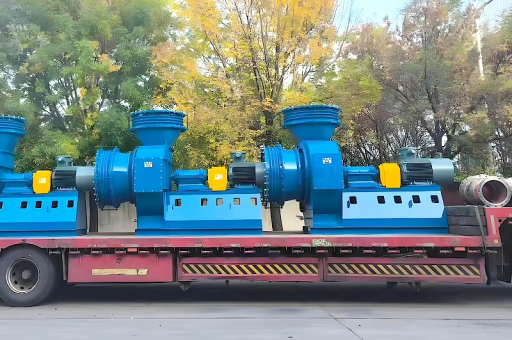
- Drive Configuration:
- Direct Drive: (Impeller mounted on motor shaft) – Highest efficiency, no belt losses. Requires a variable frequency drive (VFD) for speed control.
- Belt Drive: Allows for speed changes via pulley ratio. More flexible for retrofits but has ~2-5% transmission loss.
- Coupling Drive: (Motor connected via a flexible coupling) – Common for very large fans with separate bearings.
- Control Mechanism:
- Inlet Guide Vanes (IGVs): Common for this size fan. They pre-swirl the air to reduce flow efficiently.
- Variable Speed Drive (VSD/VFD): The most efficient method for partial load operation, especially for large ID and FD fans in power plants.
- Damper/Throttle: Inefficient, but simple. Only for baseline applications.
Summary Table
| Parameter | Value | Classification |
|---|---|---|
| Impeller Ø | 800 – 2950 mm | Large Industrial |
| Max Flow | 810,000 m³/h | Very High Volume |
| Max Pressure | 7218 Pa | Medium-High |
| Efficiency Target | 82 – 88% (Static) | High Efficiency |
| Blade Type | Backward Curved / Airfoil | Industrial Standard |
| Typical Power | 55 kW – 1500+ kW | High Power |