This article's table of contents introduction:

- Table of Contents
- Introduction: The Role of High-Power Induced Draft Fans
- Technical Design and Performance Parameters of 160kW Systems
- Operating Principles: Centrifugal Force and Dust Separation
- Key Components and Material Selection for Durability
- Comparison with Axial Fans and Lower-Power Alternatives
- Common Questions and Expert Answers (Q&A)
- Installation, Maintenance, and Energy Efficiency Considerations
- Safety Regulations and Industry Standards
- Future Trends and Smart Integration in Dust Control
- Conclusion: Why 160kW Fans Are a Cornerstone of Heavy Industry
Table of Contents
- Introduction: The Role of High-Power Induced Draft Fans
- Technical Design and Performance Parameters of 160kW Systems
- Operating Principles: Centrifugal Force and Dust Separation
- Key Components and Material Selection for Durability
- Comparison with Axial Fans and Lower-Power Alternatives
- Common Questions and Expert Answers (Q&A)
- Installation, Maintenance, and Energy Efficiency Considerations
- Safety Regulations and Industry Standards
- Future Trends and Smart Integration in Dust Control
- Conclusion: Why 160kW Fans Are a Cornerstone of Heavy Industry
Introduction: The Role of High-Power Induced Draft Fans
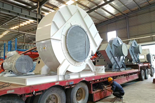
In heavy industrial environments—such as cement plants, steel mills, chemical processing facilities, and biomass power stations—airborne particulate matter presents significant health, safety, and operational challenges. The 160kW dust removal centrifugal induced draft fan stands as a critical piece of equipment designed to move large volumes of dust-laden air against substantial system resistance. Unlike general ventilation fans, these units generate negative pressure (induced draft) to capture contaminants at the source and transport them to filtration systems such as baghouses or electrostatic precipitators.
The 160kW power rating places this fan in the heavy-duty category, capable of handling airflows exceeding 150,000 cubic meters per hour and static pressures up to 8,000 Pa, depending on impeller design and speed. This article examines the engineering, application, and optimization of this specific equipment class, drawing on verified technical data and industry best practices.
Technical Design and Performance Parameters of 160kW Systems
A 160kW centrifugal induced draft fan is typically driven by an electric motor coupled directly or through a V-belt drive. Performance is defined by three primary curves: flow rate (Q), static pressure (ΔP), and efficiency (η).
- Flow Capacity: For dust removal, these fans commonly operate in the range of 120,000 to 180,000 m³/h at working conditions.
- Static Pressure: Typical design points range from 4,000 to 7,500 Pa, accounting for duct losses, filter resistance (which increases as bags load), and local friction.
- Impeller Configuration: Backward-curved blades are standard for dust applications because they are less prone to material buildup and offer non-overloading power characteristics.
- Speed: Operating speeds of 800 to 1,200 RPM allow for robust torque while minimizing wear.
The impeller diameter for a 160kW fan generally falls between 1,500 mm and 2,200 mm, with the housing designed to withstand abrasive particle impact. Materials such as Corten steel, HARDOX 400, or high-chrome castings are used for liners and blades, depending on particle size and abrasiveness.
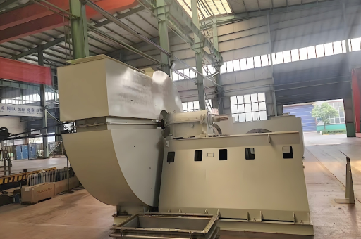
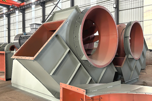
Operating Principles: Centrifugal Force and Dust Separation
The fundamental mechanism relies on the centrifugal acceleration of air and particulates. Air enters the impeller axially through the inlet cone, turns 90 degrees, and is expelled radially outward by rotating blades. This action creates a low-pressure zone at the inlet, drawing in dust-laden air from hoods, ducts, or enclosures.
Key physics:
- The tangential velocity imparted by the blades generates a pressure rise across the impeller.
- The volute housing converts high-velocity dynamic pressure into static pressure, overcoming system resistance.
- Dust particles, due to their higher density, experience greater centrifugal force and tend to concentrate near the housing wall. In many designs, a bleed-off or pre-separator slot can route coarse particulate directly to a disposal bin before air reaches the filter.
This design reduces the burden on downstream filter cartridges, extending service intervals and lowering compressed air consumption for pulse-jet cleaning.
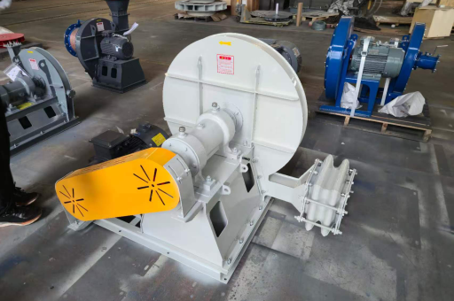
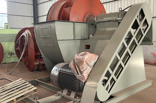
Key Components and Material Selection for Durability
Given the dust load and continuous operation (often 24/7), component durability is critical.
- Impeller: Fabricated from welded alloy steel or cast in wear-resistant iron. Some designs use replaceable tip strips to extend service life.
- Shaft and Bearings: Heavy-duty spherical roller bearings housed in cast-iron pillow blocks. Temperature sensors and vibration probes are standard for predictive maintenance.
- Housing Liner: Removable wear plates made of ceramic tiles or hard-faced steel protect the volute from erosion.
- Inlet Damper or Vane Control: A variable inlet guide vane instead of a damper improves part-load efficiency. However, for dust-laden air, dampers may suffer from fouling.
- Sealing System: Labyrinth seals or purge air systems prevent dust migration into bearing housings.
Material choices are increasingly guided by lifecycle cost analysis rather than initial procurement price, as downtime replacement costs can exceed the fan’s capitalized value within weeks in high-utilization plants.
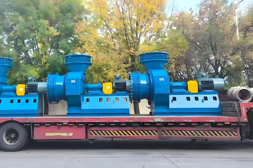
Comparison with Axial Fans and Lower-Power Alternatives
A common selection question: why choose a 160kW centrifugal induced draft fan over a similarly sized axial fan?
| Parameter | 160kW Centrifugal (ID Fan) | Axial Fan (Comparable Power) |
|---|---|---|
| Pressure capability | High (up to 8,000+ Pa) | Low to moderate (max ~2,000 Pa) |
| Efficiency at high pressure | 75–85% | declines above 800 Pa |
| Dust handling | Excellent with backward blades | Poor; particles erode blades |
| Noise level | Moderate (85–95 dB(A)) | Higher (100+ dB(A) at full speed) |
| Space requirement | Larger footprint | Compact, duct-mounted |
For dust collector services requiring high static pressure to overcome filter cake resistance, the centrifugal design remains the industry standard. Lower-power fans (e.g., 75kW or 110kW) may suffice for smaller systems or lower-dust conditions, but 160kW units are optimal for handling the combined duties of larger baghouses or multiple collection points.
Common Questions and Expert Answers (Q&A)
Q1. What is the typical lifespan of a 160kW dust removal fan in abrasive service? A: With proper impeller coating (e.g., chrome carbide overlay), you can expect 3–5 years before major refurbishment. Replacement of wear liners and balancing every 18–24 months extends operational life to 8–10 years.
Q2. How do I calculate the required motor power for my specific dust system? A: Use the formula: P (kW) = (Q × ΔP) / (1000 × η_fan × η_drive). Assume Q in m³/s and ΔP in Pa. For dust fans, multiply by a safety factor of 1.1 to account for filter loading. A typical 160kW motor operates at around 90–93% efficiency at full load.
Q3. Can a 160kW fan be retrofitted into an existing 132kW duct system? A: Yes, but you must evaluate the duct gauge (to handle higher static pressure), motor starter sizing, and bearing deck loads. A fan upgrade without duct reinforcement can cause duct collapse or vibration issues.
Q4. What are the most common failure modes for large induced draft fans? A: Unbalance due to uneven dust buildup on impeller blades; bearing fatigue from prolonged operation near critical speed; and erosion of the impeller eye plate.
Q5. Is variable frequency drive (VFD) recommended for this power class? A: Strongly recommended for process control. VFDs reduce energy consumption by 20–40% when the fan operates at 70–90% flow. However, harmonic filters may be required to meet IEEE 519 guidelines, and the VFD must have a dust-proof enclosure (IP55 or higher).
Installation, Maintenance, and Energy Efficiency Considerations
Installation best practices:
- Foundation: A reinforced concrete inertia block weighing at least three times the fan weight is essential to damp vibration.
- Isolation: Use steel spring isolators or neoprene pads to decouple the fan from the building structure.
- Duct transitions: Avoid sharp bends within five duct diameters upstream of the inlet to prevent turbulent airflow that reduces efficiency and causes premature wear.
Maintenance schedule:
- Daily: Visual inspection for oil leaks, unusual noise, or vibration spikes.
- Weekly: Check pressure drop across the filter; clean inlet screen if present.
- Monthly: Grease bearings if using manual lubrication; measure motor current draw.
- Annually: Remove impeller for cleaning, crack inspection, and dynamic balancing.
Energy savings opportunities:
- Replace throttling dampers with VFDs (commonly recovers 15–25% energy).
- Ensure ductwork is sealed; leaks can increase airflow demand by 10–15%.
- Replace standard motors with IE4 or IE5 efficiency class units for continuous operation.
A detailed energy audit of a 160kW fan running 8,000 hours per year reveals that moving from 95% to 97% efficiency saves approximately 25,000 kWh annually—equivalent to roughly 10 metric tons of CO₂ reduction (at average grid mix) and $2,500 in operating cost at typical industrial electricity rates.
Safety Regulations and Industry Standards
Compliance with international standards ensures both operator safety and equipment reliability:
- ISO 14694: Specifies balance quality grades for fans (Grade G6.3 or G2.5 for dust fans).
- ISO 5801: Defines test procedures for performance measurement.
- ATEX Directive 2014/34/EU: For fans handling combustible dust (e.g., wood, coal, sulfur), the impeller must be spark-resistant (aluminum/bronze or non-metallic tips) and the housing must include explosion vent panels.
- OSHA 1910.107 (US): Requires spark detection and suppression systems for fans in paint or grain dust environments.
Manufacturers should provide CE or UL certification for the entire fan-motor-drive assembly.
Future Trends and Smart Integration in Dust Control
The 160kW dust removal centrifugal induced draft fan is evolving with Industry 4.0 technologies:
- Real-time condition monitoring: Vibration sensors, thermal cameras, and acoustic emission sensors connect to cloud-based machine learning models that predict bearing failure 72 hours in advance.
- Adaptive speed control: AI-based controllers adjust fan speed in response to real-time baghouse differential pressure and emission monitoring data, optimizing energy use while ensuring compliance with particulate matter limits (e.g., US EPA 40 CFR Part 60).
- Material innovation: 3D-printed impeller blades with lattice structures to reduce weight while maintaining strength are currently in pilot trials.
- Hybrid drives: Coupling regenerative braking motors with energy storage to capture kinetic energy during load reduction phases.
Conclusion: Why 160kW Fans Are a Cornerstone of Heavy Industry
The 160kW dust removal centrifugal induced draft fan is not merely a motor and impeller; it is a precision engineered system that balances aerodynamic performance, material resilience, and energy efficiency in some of the world’s harshest environments. Its ability to generate high static pressure while handling abrasive particulates makes it indispensable for meeting emission regulations and protecting worker health.
Specifying the correct fan—accounting for dust type, temperature, humidity, and filter loading characteristics—separates a reliable installation from one plagued by breakdowns. As sustainability pressures grow, pairing this fan with VFDs, smart sensors, and high-efficiency motors will unlock further operational savings. For engineers and facility managers, understanding the nuances of this equipment class ensures cleaner air, lower costs, and greater process uptime.
For those seeking to specify or upgrade a dust control system, remember: Fan selection is an investment in both compliance and productivity.