This article's table of contents introduction:

- What is an Incinerator Exhaust Fan?
- Critical Functions & The Harsh Environment
- Key Design Features & Materials of Construction
- Types of Incinerator Exhaust Fans
- Where is the Fan Located in the System?
- Common Problems & Maintenance
- Summary Table: ID Fan vs. FD Fan
Here is a comprehensive overview of Incinerator Exhaust Fans, covering their purpose, key features, design considerations, and types.
What is an Incinerator Exhaust Fan?
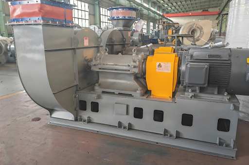
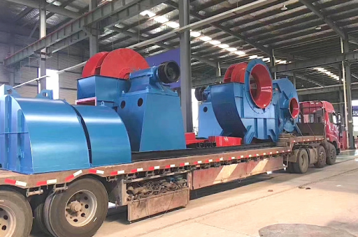
An incinerator exhaust fan is a specialized, heavy-duty industrial fan designed to handle the extreme conditions of an incineration process. Its primary function is to create negative pressure (draft) within the incinerator, primary chamber, secondary chamber, and ductwork.
This negative pressure ensures:
- Safety: Prevents hot, toxic flue gases and flames from escaping into the surrounding environment.
- Efficiency: Pulls combustion air into the incinerator and ensures the hot gases travel through the system to the afterburner and stack.
- Emissions Control: Moves gases through pollution control equipment (scrubbers, baghouses) before release to the atmosphere.
Critical Functions & The Harsh Environment
Unlike standard HVAC fans, incinerator exhaust fans operate in an incredibly challenging environment:
- Extreme Temperatures: Gas temperatures entering the fan can range from 350°F (175°C) up to 1000°F (538°C) in some applications (especially if the fan is located before a heat recovery or cooling system). Pre-heated or "tempering" air is sometimes added to protect the fan from thermal damage.
- Corrosive Gases: Combustion byproducts (especially from medical, hazardous, or municipal waste) contain acids like HCl, SOx, and NOx. These can rapidly destroy standard carbon steel.
- Abrasive Particulates: Fly ash, dust, and other solid particles from the burning waste erode fan blades and housing.
- Potential for Sticky or Stubborn Buildup: Tars, resins, and other organic compounds can condense and stick to fan blades, causing imbalance and vibration.
Key Design Features & Materials of Construction
Because of the harsh conditions, these fans are built to a much higher standard.
| Feature | Material / Design Details |
|---|---|
| Housing (Casing) | Typically heavy-gauge steel. For corrosion resistance: Stainless Steel (304/316L) or Alloy (Hastelloy, Inconel) . For abrasion: Corten steel with replaceable wear liners. |
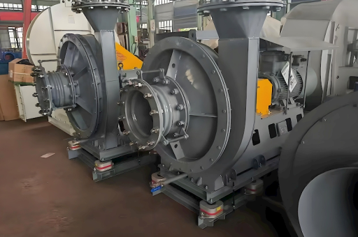
| Wheel / Impeller | Radial (paddlewheel) or radial-tip design. These are flat-bladed wheels that are easy to clean, less prone to material buildup, and highly resistant to thermal expansion and abrasion. They are not forward-curved (inefficient for dirty gas) or backward-inclined (too fragile). |
| Shaft | Large diameter, high-strength alloy steel. Often enclosed in a shaft cooling shroud or cooled by ambient air to prevent heat transfer to bearings. |
| Bearings | Heavy-duty spherical roller bearings. These are located outside the fan housing in a separate pedestal (air-over design) or have a cooling system. They must handle high radial and axial loads. |
| Shaft Seal | Critical to prevent gas leakage. Types include: • Mechanical Seals (for tight sealing) • Packing Glands (with purge air) • Labyrinth Seals (with inert gas purge) |
| Cooling | • Shaft Cooling Fan: A small fan on the motor side pushes cool air over the shaft. • Water Jacket: On the fan housing near the shaft entry point. • Tempering Air Inlet: Ambient air is ducted into the fan inlet to reduce gas temperature. |
| Drive System | Typically direct-coupled or V-belt driven. A Variable Frequency Drive (VFD) is almost mandatory to control draft and system pressure precisely. |
Types of Incinerator Exhaust Fans
- Radial (Paddlewheel) Fan: The most common type. Simple, rugged, self-cleaning, and excellent for high temperatures and abrasive dust. The flat blades radiate outward from the hub.
- Radial-Tip Fan: A modification of the paddlewheel. The blade tips are curved forward (in the direction of rotation) to reduce noise and improve efficiency slightly while maintaining ruggedness.
- Pressure Blower: Used for smaller incinerators or to provide combustion air, not exhaust. High pressure, lower volume.
- Axial Fan (e.g., Vaneaxial): Rarely used for the main exhaust. Used for lower pressure, higher flow applications like dilution air or cooling air. They are not robust enough for the main flue gas.
Where is the Fan Located in the System?
The fan's location drastically changes its operating conditions:
- Induced Draft (ID) Fan (Most Common): Located after the incinerator and pollution control equipment. This is the safest option as the gases have been partially cooled and scrubbed by the time they reach the fan. The fan "pulls" the gas through the entire system (incinerator -> heat exchanger -> scrubber -> baghouse -> fan -> stack).
- Forced Draft (FD) Fan: Located before the incinerator. It blows combustion air into the burner. This fan sees clean, ambient air and is much simpler to design.
- Booster Fan: Located after a specific piece of equipment (e.g., after a scrubber) to overcome pressure drop, before the stack.
Common Problems & Maintenance
- Vibration: Caused by:
- Imbalance: Ash buildup on blades, especially after a shutdown when condensation occurs.
- Erosion: Uneven wear of blades.
- Thermal Distortion: Casing or wheel warped from uneven heating.
- Corrosion: Most commonly at the weld joints or the blade roots. Regular inspections and coating maintenance are critical.
- Bearing Failure: The #1 cause of fan failure. Due to high shaft temperatures, vibration, and contaminants. Routine lubrication and temperature monitoring are essential.
- Seal Leakage: Causes dangerous gas leaks. Requires immediate attention.
Summary Table: ID Fan vs. FD Fan
| Feature | Induced Draft (ID Fan) | Forced Draft (FD Fan) |
|---|---|---|
| Location | After the process, before the stack | Before the process (blower) |
| Gas Medium | Hot, corrosive, dirty flue gas | Clean, ambient air |
| Construction | Heavy-duty, alloy, abrasion-resistant | Standard duty, carbon steel |
| Cooling | Shaft cooling, tempering air required | Not required |
| Key Challenge | Corrosion, erosion, high temperature | High pressure, noise |
Conclusion: An incinerator exhaust fan is a critical piece of equipment that must be robustly engineered for its specific gas temperature, chemical composition, and particulate load. Proper material selection, a radial impeller design, external bearings, and a VFD are essential for reliable and safe operation.