This article's table of contents introduction:

- Core Components
- How it Works (The Fan Laws)
- Common Applications
- Critical Advantages of VFD Control (vs. Damper/Valve Control)
- Potential Problems & Solutions
- Installation & Sizing Guidance
- Summary Checklist for a 22kW VFD Centrifugal Fan
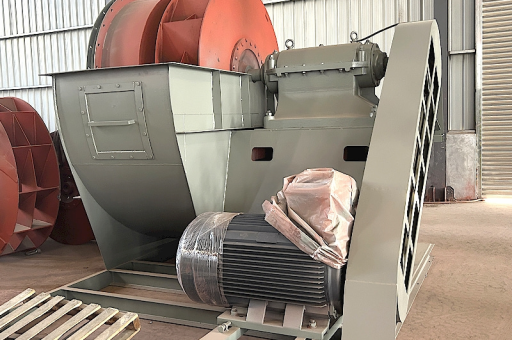
This is a common and powerful industrial setup. A 22kW (kilowatt) variable frequency centrifugal fan is a high-capacity system used for moving large volumes of air against significant resistance (static pressure).
Here is a comprehensive breakdown of what this entails, from the components to typical applications and troubleshooting.
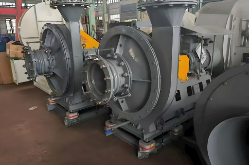
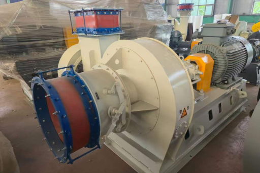
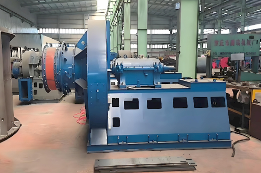
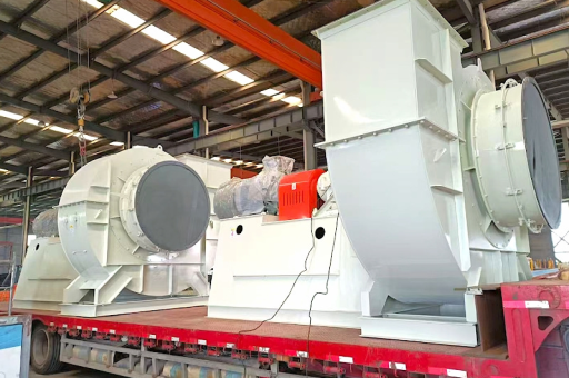
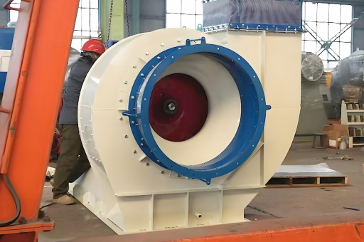
Core Components
-
Centrifugal Fan: The air mover. It uses a rotating impeller to increase air velocity and pressure. Common types include:
- Backward Curved: High efficiency, non-overloading power curve (good for VFD control).
- Forward Curved: High volume at low pressure, often smaller/more compact.
- Radial Blade: For harsh/dusty air, handles high pressure but is less efficient.
-
22kW Motor: The prime mover. Almost always a 3-phase induction motor (typically 4-pole, 1450-1500 RPM at 50Hz or 1750-1800 RPM at 60Hz).
- Voltage: Typically 380-415V (50Hz) or 460-480V (60Hz), depending on region.
- Full Load Current (FLC): Varies by voltage. A 22kW motor at 400V 3-phase draws roughly 40-42 Amps. Check the nameplate.
-
Variable Frequency Drive (VFD): The speed controller.
- Rating: Must be sized for the motor's full load current (FLC), not just the power. A 22kW motor often requires a 22kW or 25kW/30kW VFD.
- Function: Converts AC mains power to variable frequency/voltage to control motor speed from ~0% to 100%.
-
Control System: The brain. Can be:
- Local Panel: Potentiometer, start/stop buttons, selector switch.
- PLC/DCS: Remote control via 4-20mA or 0-10V signal.
- PID Controller: For closed-loop control (e.g., maintaining constant duct pressure or temperature).
How it Works (The Fan Laws)
The combination of a VFD and a centrifugal fan follows the Affinity Laws. This is the key to energy savings:
- Flow (Air Volume) ∝ Speed: Half the speed = Half the airflow.
- Pressure ∝ Speed²: Half the speed = Quarter the pressure.
- Power ∝ Speed³: Half the speed = Eighth (12.5%) of the power.
Example: A 22kW fan running at 100% speed draws 22kW. If you only need 80% airflow, you only run the fan at 80% speed. Power required = 22kW (0.8)³ = 22kW 0.512 = ~11.2 kW. You save over 50% energy.
Common Applications
- HVAC: Large building air handling units (AHU), exhaust systems.
- Industrial Ventilation: Dust collection, fume extraction in factories/welding shops.
- Process Air: Drying systems, pneumatic conveying, combustion air for burners.
- Mining/Tunneling: Primary ventilation fans.
Critical Advantages of VFD Control (vs. Damper/Valve Control)
- Massive Energy Savings: As shown above, the cubic power relationship is highly efficient.
- Soft Start: The motor accelerates gradually, eliminating high inrush current (up to 600% of FLC). This reduces electrical stress and mechanical shock (belt snapping, bearing wear).
- Process Control: Precise, repeatable control of airflow or pressure.
- Reduced Maintenance: No moving parts for flow control (like damper linkages), lower motor/fan stress.
Potential Problems & Solutions
| Problem | Likely Cause | Solution |
|---|---|---|
| VFD trips on Overcurrent | Fan speed too high, blocked duct, or VFD parameters wrong | Check for blockage, verify motor FLC in VFD, reduce acceleration time. |
| VFD trips on Overvoltage | Rapid deceleration (regeneration) or high incoming line voltage | Increase deceleration time, add a braking resistor, fix input voltage. |
| Motor Overheating | Fan running below 30% speed (insufficient motor cooling), VFD carrier frequency high, or harmonics | Use a motor with separate forced cooling (TEFC with blower), reduce carrier frequency (may cause motor noise). |
| Vibration / Noise | Impeller imbalance, bearing wear, or resonance at specific VFD frequency | Re-balance impeller, check bearings, use VFD "skip frequencies" to avoid resonance. |
| Reduced Airflow | Duct leak, belt slip, or impeller rotation wrong direction | Check belts, verify impeller spins in the correct direction (arrow on housing). |
Installation & Sizing Guidance
- Cable Size: For a 22kW motor at 400V (~40A FLC), use a 6mm² to 10mm² (10 AWG to 6 AWG) 4-core armored cable. Check local electrical codes.
- VFD Location: Install in a cool, clean, dry area (IP54 cabinet minimum). Overheating is the #1 killer of VFDs.
- Braking Resistor: A 22kW fan has high inertia. If you need to stop it quickly (e.g., for emergency stops or frequent cycling), you will need a braking resistor connected to the VFD. Without it, the drive will trip on overvoltage during deceleration.
- Minimum Speed: For a standard TEFC motor, do not run the fan continuously below 20-25% of max speed (e.g., 300 RPM on a 1440 RPM motor) unless the motor has an auxiliary cooling fan. The motor's internal fan will spin too slowly to remove heat.
Summary Checklist for a 22kW VFD Centrifugal Fan
- [ ] Fan Selection: Matches required CFM and Static Pressure.
- [ ] Motor: 3-phase, correct voltage, FLC within VFD rating.
- [ ] VFD: Properly sized (FLC), programmed for pump/fan curve (Square Law, not Constant Torque).
- [ ] Cabling: Screened/armored cable from VFD to Motor (minimize crosstalk).
- [ ] Braking: Resistor fitted if rapid deceleration is needed.
- [ ] Control: 4-20mA signal or digital inputs wired correctly.
- [ ] Safety: Emergency stop wiring, lockout/tagout procedures.
Which part of this setup are you focusing on? Are you sizing a new system, troubleshooting a fault, or looking for the best VFD model?