This article's table of contents introduction:

- What is a Flue Gas Return Exhaust Fan?
- Core Function: Flue Gas Recirculation (FGR)
- Key Differences from a Standard ID Fan
- Design & Construction Challenges
- Common Applications
- Typical System Diagram & Flow
- Operational Considerations
- Summary Analogy
Here is a comprehensive explanation of a Flue Gas Return Exhaust Fan, also commonly referred to as a Flue Gas Recirculation (FGR) Fan or Rekushafan (Re:Gas Fan).
What is a Flue Gas Return Exhaust Fan?
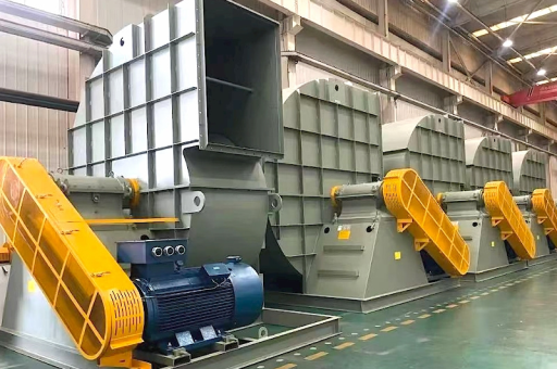
A Flue Gas Return Exhaust Fan is a specialized industrial fan designed to extract a portion of the hot exhaust gases (flue gas) from a combustion process (like a boiler, furnace, or gas turbine) and transport them back into the combustion air stream or furnace.
Its primary purpose is not to vent the gas to the atmosphere, but to recirculate it.
Core Function: Flue Gas Recirculation (FGR)
The fan is a critical component of the Flue Gas Recirculation (FGR) system, a widely used NOx (Nitrogen Oxide) reduction technique.
- The Problem: In high-temperature combustion (e.g., in power plants, industrial boilers), oxygen (O₂) and nitrogen (N₂) in the combustion air combine to form NOx, a harmful pollutant.
- The Solution: The FGR fan takes a portion of the cool, inert flue gas (primarily CO₂, N₂, and H₂O) and mixes it with the incoming combustion air.
- The Result:
- Lower Oxygen Concentration: The inert gas replaces some of the oxygen in the combustion zone.
- Lower Flame Temperature: The inert gas absorbs heat, cooling the flame peak temperature.
- Reduced NOx: Lower temperature and lower O₂ drastically reduce the formation of thermal NOx (Zeldovich mechanism).
Key Differences from a Standard ID Fan
It's important not to confuse this fan with a standard Induced Draft (ID) Fan.
| Feature | Flue Gas Return (FGR) Fan | Induced Draft (ID) Fan |
|---|---|---|
| Purpose | Recirculates gas back to the combustion air inlet. | Pulls flue gas through the system and exhausts it up the stack. |
| Gas Destination | Combustion air duct / Windbox | Chimney / Stack |
| Gas Composition | Mix of CO₂, N₂, H₂O, low O₂ | Same, but at lower pressure |
| Operating Temp | Hot (typically 250°F - 400°F / 120°C - 200°C) | Hot (but often post-cooling equipment) |
Design & Construction Challenges
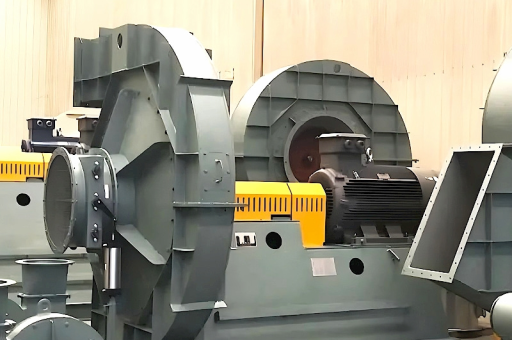
These fans operate in a very hostile environment. They must be robustly designed:
- High Temperature: The fan handles hot exhaust gas. The impeller and housing must be made from materials that resist thermal expansion and creep (e.g., Corten steel, stainless steel, or Inconel for very high temps).
- Abrasion (Erosion): Flue gas contains fly ash and other particulate matter. The fan blades and casing liners are often coated with hard-facing materials (e.g., Stellite, ceramic tiles) or made thicker to resist erosion.
- Corrosion: If the flue gas temperature drops below the acid dew point (typically around 250°F / 120°C for sulfur-bearing fuels), sulfuric acid will form and rapidly corrode the fan. The fan casing often has drains and lagging/insulation to prevent this.
- Variable Speed / Control: To accurately control the recirculation rate (typically 10-30% of total flue gas), these fans are almost always driven by Variable Frequency Drives (VFDs) or inlet guide vanes.
Common Applications
- Industrial Boilers: Coal, oil, natural gas, or biomass boilers in power plants and manufacturing facilities.
- Gas Turbines: In combined cycle power plants for NOx reduction in the heat recovery steam generator (HRSG).
- Cement Kilns & Other Process Heaters: To control flame temperature and NOx.
- Waste Incinerators: To ensure complete combustion and reduce harmful emissions.
Typical System Diagram & Flow
- Boiler / Furnace: Combustion takes place, producing flue gas.
- Downstream Duct: The flue gas exits the boiler, often passing through superheaters, economizers, or air heaters.
- Tap-Off Point: A duct branches off from the main flue gas stream downstream of the air heater (where the gas is coolest but still hot).
- FGR Fan (This Fan): Pulls the re-circulated gas from the tap-off point.
- Control Damper / VFD: Regulates the volume of gas being recirculated.
- Mixing Point: The re-circulated gas is injected into the combustion air duct (forced draft fan discharge) or directly into the windbox.
- Combustion Air + FGR: The diluted mixture enters the burner for lower NOx combustion.
Operational Considerations
- Startup: FGR fans should generally not be started until the flue gas temperature is well above the acid dew point to avoid condensation and corrosion.
- Monitoring: Regular monitoring of bearing temperature, vibration (due to erosion imbalance), and fan pressure is critical.
- Maintenance: Periodic inspection for blade wear, casing erosion, and buildup of ash. The rotating assembly may need to be re-balanced or re-surfaced over time.
Summary Analogy
Think of it like a "feedback loop" for exhaust. Instead of sending all the hot exhaust out the chimney, the FGR fan takes a portion and feeds it back into the engine (the boiler) to cool down the fire, preventing the formation of a major pollutant (NOx).
In short: The Flue Gas Return Exhaust Fan is a life-extension and pollution-control component that sacrifices efficiency (by reducing peak flame temperature) in exchange for significantly lower NOx emissions.