
This article's table of contents introduction:
- The Core Principle: What the ID Fan Does in Cooling
- Key Energy Efficiency Losses
- Optimization Strategies for Efficiency
- Summary Table: Single vs. Double Inlet for Cooling
- The "Free" Efficiency Gain: Waste Heat Recovery
- Actionable Recommendation
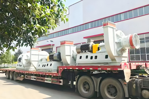
This is a very specific and technical topic. An Induced Draft (ID) Fan on a Single Inlet Kiln (often used for brick, tile, or lime production) plays a critical role in the cooling zone.
To understand the energy efficiency implications, we must look at how the fan interacts with the cooling air and waste heat recovery.
Here is a breakdown of the energy efficiency considerations, losses, and optimization strategies for an ID fan serving a single-inlet kiln’s cooling section.
The Core Principle: What the ID Fan Does in Cooling
In a single-inlet kiln (typically a tunnel kiln or a vertical shaft kiln with one main exhaust point), the ID fan is located after the kiln (downstream) to pull air through the system.
- Primary Role: It creates negative pressure inside the kiln, pulling ambient air into the cooling zone at the discharge end.
- The Conflict: The fan must pull enough cooling air to drop product temperature. However, pulling too much air or pulling it inefficiently wastes energy because:
- The fan motor consumes more power.
- Excess cold air mixes with hot exhaust gases, lowering the temperature of waste heat recovery systems (boilers or dryers).
Key Energy Efficiency Losses
A. Over-drafting (The Single Inlet Trap)
- Problem: A single-inlet kiln is much more sensitive to pressure drops than a multi-inlet system. To cool the center of the product setting, operators often increase fan speed. This creates high negative pressure at the bottom of the kiln.
- Impact: Cold air is sucked in through cracks and the car bottom system in the cooling zone. This air bypasses the product (it doesn't cool it effectively) and mixes with the hot air, increasing the total volume the fan must move. The fan works harder but doesn't improve cooling.
B. High Stack Temperature from Poor Heat Transfer
- Problem: If the cooling zone is too short or the product is densely packed (typical in single-inlet kilns), the ID fan doesn't remove heat efficiently. The air leaves the kiln at a high temperature.
- Impact: The fan is moving extremely hot, low-density air. While this sounds efficient (sensible heat is high), it often means the fan is pulling too much volume to achieve the target product temperature. The fan brake horsepower (BHP) increases exponentially with volume.
C. Parasitic Load (Over-cooling)
- Problem: Operators often run the fan at a fixed speed (e.g., damper controlled) to "guarantee" cooling. This overcools the product but wastes significant energy.
- Impact: The fan runs at 100% speed while a damper is 50% closed. This is the worst-case scenario for VFDs and energy.
Optimization Strategies for Efficiency
To improve the energy efficiency of the ID fan in a single-inlet kiln cooling zone, focus on these three areas:
A. Variable Frequency Drive (VFD) + Pressure Control
- Action: Replace damper control with a VFD. Control the fan speed based on a static pressure sensor in the cooling zone, not a temperature sensor.
- Efficiency Gain: Running a fan at 80% speed consumes ~50% less power than running it at 100% speed. A VFD on an ID fan in a kiln typically yields a 15-25% electrical energy savings.
B. Air Sealing & Zone Pressurization
- Action: Seal the kiln car bottom and the cooling zone entry point. If the kiln is a single-inlet design, consider adding a small recirculation fan in the cooling zone to push air through the product rather than relying solely on the ID fan to pull it.
- Efficiency Gain: Reduces the "short-circuit" air flow. The ID fan doesn't have to move useless air. This lowers the total system pressure drop.
C. Thermal Performance Analysis (The "ΔT" Method)
- Action: Monitor the temperature of the air entering the ID fan duct. If this temperature is very high (e.g., > 250°C / 482°F), it suggests poor heat transfer in the cooling zone. If it is low (e.g., < 50°C / 122°F), you are likely over-drafting.
- Ideal Range: For most single-inlet kilns, the ideal exhaust temperature for energy efficiency is 120°C - 160°C (248°F - 320°F) . This allows for good product cooling without wasting fan energy.
Summary Table: Single vs. Double Inlet for Cooling
| Feature | Single Inlet Kiln (ID Fan) | Double Inlet Kiln (Often more efficient) |
|---|---|---|
| Air Flow Path | Air enters at one end, pulled through. | Air enters at top & bottom/ or multiple points. |
| ID Fan Load | Higher static pressure required to pull through dense product. | Lower static pressure; better distribution. |
| Efficiency Tip | Critical: Install VFD & seal kiln car gaps. | Critical: Balance dampers between inlets. |
| Typical Loss | Over-drafting at the bottom of the car. | Uneven cooling (hot/cold spots in product). |
The "Free" Efficiency Gain: Waste Heat Recovery
Since you are moving cooling air, consider this: The hottest air from the cooling zone (right after the product exits) is the most valuable.
- Action: Install a bypass damper on the cooling zone. This allows you to route the hottest 15% of the cooling air directly to a heat exchanger (for drying or boiler feed water preheat) without passing it through the ID fan.
- Benefit: The ID fan moves less total volume (lower energy), and you capture high-grade heat.
Actionable Recommendation
If you are operating a single-inlet kiln with an ID fan for cooling:
- Install a pressure transducer at the start of the cooling zone (1-2 meters from the kiln exit).
- Install a VFD on the ID fan.
- Set the control loop to maintain a set point of slightly negative pressure (e.g., -0.5 to -1.0 inWC) rather than a specific speed or temperature.
- Monetize the waste heat. The energy you save on the fan is secondary to the energy you save by using that hot air for drying or combustion air preheat.
Conclusion: The single biggest energy efficiency gain for an ID fan in a single-inlet kiln cooling zone is switching from temperature-based control to pressure-based control with a VFD. This directly reduces the parasitic losses of over-drafting.





