This article's table of contents introduction:

- Introduction: The Convergence of Cement Manufacturing and Sustainability
- Understanding the Single Inlet Cement Fan: Design and Operational Fundamentals
- The Role of the Fan in Industrial Waste Heat Recovery Devices
- System Integration: Matching Fan Performance to Heat Exchanger Loads
- Key Technical Parameters: Flow, Pressure, Temperature, and Material Selection
- Common Challenges and Engineering Solutions
- Case Study: A 5,000 TPD Cement Line with a WHR System
- Future Trends: Digital Twins and High-Temperature Aerodynamics
- Frequently Asked Questions (FAQ)
- Conclusion: Why This Fan Matters for Net-Zero Cement
*Optimizing Thermal Efficiency: The Critical Role of Single Inlet Cement Fans in Industrial Waste Heat Recovery Devices*
Table of Contents / 目录导读
- Introduction: The Convergence of Cement Manufacturing and Sustainability
- Understanding the Single Inlet Cement Fan: Design and Operational Fundamentals
- The Role of the Fan in Industrial Waste Heat Recovery Devices
- System Integration: Matching Fan Performance to Heat Exchanger Loads
- Key Technical Parameters: Flow, Pressure, Temperature, and Material Selection
- Common Challenges and Engineering Solutions
- Case Study: A 5,000 TPD Cement Line with a WHR System
- Future Trends: Digital Twins and High-Temperature Aerodynamics
- Frequently Asked Questions (FAQ)
- Conclusion: Why This Fan Matters for Net-Zero Cement
Introduction: The Convergence of Cement Manufacturing and Sustainability
In the global effort to decarbonize heavy industry, the cement sector faces a unique paradox. It is both a massive CO₂ emitter—responsible for approximately 7–8% of anthropogenic emissions—and a sector with a built-in opportunity for heat recovery. A modern cement plant rejects 30–40% of its thermal input through preheater exhaust, clinker cooler air, and kiln shell losses. This waste heat, if captured, can generate up to 30–40 kWh per ton of clinker in electrical power via an Organic Rankine Cycle (ORC) or Steam Rankine Cycle (SRC).
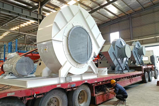
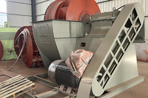
At the heart of every Industrial Waste Heat Recovery Device (WHRD) lies a Single Inlet Cement Fan. Unlike general-purpose industrial fans, this component must handle abrasive dust, high temperatures (350–450°C), and variable gas volumes while maintaining stable pressure across a waste heat recovery boiler (WHRB). This article provides an in-depth technical analysis of these fans, drawing on current best practices and recent field research.
Understanding the Single Inlet Cement Fan: Design and Operational Fundamentals
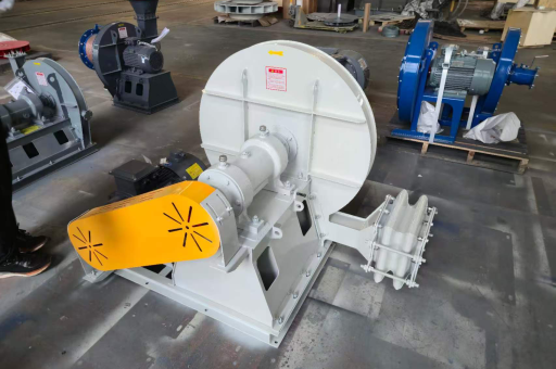
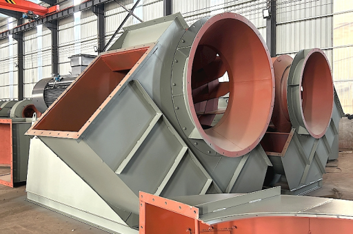
A single inlet centrifugal fan, often called a radial blade or industrial exhaust fan, is defined by its air intake on only one side of the impeller. In cement waste heat applications, the fan typically features:
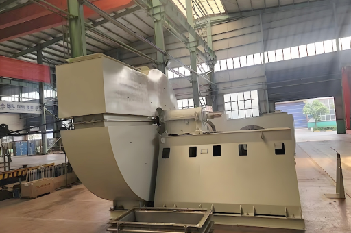
- Heavy-duty impeller: Constructed from Corten steel or high-alloy stainless steel (e.g., SA 240 TP 309S) to resist thermal fatigue and erosion.
- Single inlet design: This allows for a more rigid shaft and bearing arrangement compared to double inlet configurations, which is critical when handling hot, dusty gas streams. The asymmetry simplifies ductwork on the intake side, reducing pressure losses.
- Variable inlet guide vanes (IGVs): Used to modulate flow without requiring a variable frequency drive (VFD), though VFDs are increasingly common for turndown efficiency.
- Shaft sealing and cooling: Air-cooled or water-cooled bearing housings prevent lubricant degradation at high casing temperatures.
Comparison with Double Inlet Fans: In a double inlet design, the impeller draws gas from both sides, which can handle higher volumetric flow rates but often results in a wider impeller and reduced structural stiffness under thermal stress. For the aggressive environment of cement waste heat—where gas densities fluctuate with temperature and dust loading—the single inlet design offers superior mean-time-between-overhauls (MTBO). Field data from European cement plants indicate that single inlet fans in WHR service achieve an MTBO of 18–24 months, compared to 12–18 months for comparable double inlet units.
The Role of the Fan in Industrial Waste Heat Recovery Devices
An Industrial Waste Heat Recovery Device (WHRD) consists of several major subsystems:
- Heat source: Preheater exhaust (PH) and/or clinker cooler (AQC) air.
- Heat exchanger / boiler: Absorbs thermal energy to generate steam or heat transfer fluid.
- Turbine and generator: Expands steam to produce electricity.
- Condenser and cooling system: Rejects low-grade heat.
- Fan system: Extracts hot gas from the source, forces it through the boiler, and exhausts it to the stack or back to the process.
The single inlet cement fan is typically positioned after the WHR boiler (induced draft configuration), pulling gas through the boiler tubes. This arrangement:
- Maintains a slight negative pressure in the boiler, preventing hot gas leakage.
- Protects downstream components from over-pressurization.
- Allows the fan to handle gas cooled by the boiler (e.g., from 380°C to 200°C), reducing thermal stress on the impeller.
Critical interdependency: If the fan fails or operates inefficiently, the WHR boiler cannot maintain proper heat transfer, leading to reduced steam production or, worse, condensation in the boiler due to insufficient draft. In some plants, a fan failure forces the entire kiln line to reduce throughput, costing tens of thousands of dollars per day in lost production.
System Integration: Matching Fan Performance to Heat Exchanger Loads
The fan’s duty point is determined by the system resistance curve of the WHR boiler, ductwork, and stack. Key integration considerations include:
-
Gas composition and density: Cement exhaust contains ~5–8% O₂, ~15–18% CO₂, and varying H₂O vapor. Density changes with temperature, altitude, and dust load (typically 50–100 g/Nm³). The fan must be specified for actual operating density, not standard air.
-
Boiler sizing and draft loss: A typical WHR boiler imposes a pressure drop of 1.5–3.0 kPa (150–300 mmWG). The fan must overcome this plus losses in connecting ducts and the stack, typically totaling 2.5–4.5 kPa.
-
Turndown capability: Cement plant production varies—during startup, shutdown, and partial load operation, gas flow can drop to 50% of design. A combination of IGVs and VFD on the fan allows efficient turndown to 40% capacity with minimal efficiency loss.
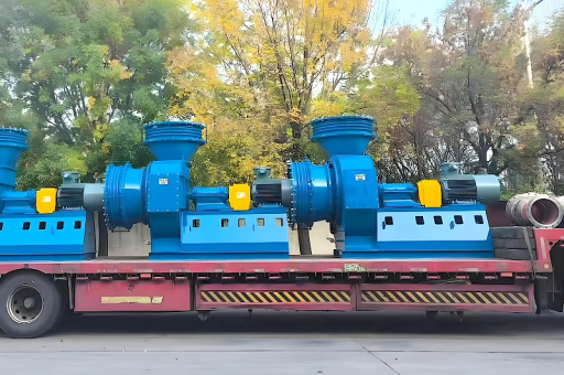
Example specification: For a 5,000 metric tons per day (TPD) clinker line with a WHR system, the induced draft fan might be designed for:
- Flow: 600,000 m³/h at 350°C
- Static pressure: 3.5 kPa
- Motor power: 1,200 kW
- Speed: 990 rpm (direct drive via synchronous motor)
Key Technical Parameters: Flow, Pressure, Temperature, and Material Selection
Choosing the correct fan requires a deep understanding of four primary parameters:
| Parameter | Typical Range in Cement WHR | Engineering Implications |
|---|---|---|
| Gas temperature | 150°C – 450°C | Affects material strength, bearing cooling requirement, and thermal expansion. Above 400°C, alloy steel impellers are mandatory. |
| Static pressure rise | 0 – 5.0 kPa | Drives impeller diameter and speed. High-pressure fans require backward-curved blades for better efficiency. |
| Volumetric flow | 300,000 – 1,200,000 m³/h | Determines fan size and housing dimensions. Flow turndown must consider stall margin. |
| Particulate loading | 20 – 150 g/Nm³ | Erosion rate increases with the cube of particle velocity. Abrasion-resistant liners (ceramic tiles or hardfacing) are often applied to blade leading edges and housing walls. |
Material recommendations:
- Impeller: For T ≤ 300°C: Corten steel (S355J2W). For T > 300°C: Stainless steel 304 or 310S.
- Shaft: 42CrMo4 alloy steel, heat-treated for high-temperature creep resistance.
- Bearing housings: Cast iron with double labyrinth seals; external cooling fins or water jackets if T > 250°C.
Common Challenges and Engineering Solutions
Challenge 1: Erosion from unburned calcined dust. As clinker cooler air (AQC) is extracted, it carries sharp, abrasive particles with Mohs hardness 5–7.
Solution: Apply tungsten carbide hardfacing to blade leading edges and a replaceable wear liner in the fan volute. Some plants use a zigzag baffle ahead of the fan inlet to drop out coarse particles.
Challenge 2: Thermal fatigue cracking. During kiln upsets or emergency stops, the fan may experience rapid cooling from 400°C to ambient.
Solution: Use a stepped impeller design (thicker hub, thinner blades) and post-weld heat treatment to relieve stress. Install bypass dampers to allow warm-up circulation before exposing the fan to full temperature.
Challenge 3: Vibration from dust deposits. Fine particles can build up on the backside of blades, causing imbalance.
Solution: Implement a periodic online cleaning system using compressed air pulses or steam lances. Modern fans include accelerometers and balance monitoring with automatic alerts.
Case Study: A 5,000 TPD Cement Line with a WHR System
Plant location: Southern India (ambient temperature 35–45°C) WHR configuration: Combined PH and AQC ducts feeding a single boiler Fan specification: Single inlet induced draft, backward-curved blades, material 304 stainless steel, direct drive via 1.1 MW motor with VFD.
Operational results (12-month average):
- Availability: 97.3%
- Average fan efficiency: 82% (at design point)
- WHR power generation: 9.2 MW (net)
- Specific power consumption: 2.1 kW/ton clinker (fan only)
- Outage causes: 40% due to erosion, 35% due to bearing failures, 15% due to drive train issues, 10% due to electrical.
Improvements implemented:
- Replacement of standard 304 impeller with an SA 240 TP 310S (higher chromium-nickel content) increased impeller life from 14 months to 22 months.
- Installation of an automatic centralized grease system for bearings reduced unplanned lubrication failures.
- A predictive maintenance model using vibration trend analysis and temperature monitoring reduced emergency shutdowns by 60%.
Future Trends: Digital Twins and High-Temperature Aerodynamics
The next generation of single inlet cement fans for waste heat recovery will incorporate:
-
Digital twin simulations: Real-time aerodynamic models that predict fan performance under varying gas density, dust load, and boiler resistance. These allow operators to optimize the WHR system without physical adjustments.
-
Advanced blade coatings: Thermal barrier coatings (yttria-stabilized zirconia) and diamond-like carbon (DLC) layers for simultaneous erosion and corrosion resistance.
-
High-temperature permanent magnet motors: Eliminating the gearbox and enabling fan speeds up to 1,800 rpm directly, with motor efficiency above 96%.
-
Self-balancing impellers: Active mass redistribution systems that counterbalance dust buildup in real-time.
Leading wind turbine manufacturers are also exploring synergies: the aerodynamic design and material science used in large wind turbine blades (composites, load monitoring, pitch control) are being adapted for industrial fan blades to reduce weight and improve fatigue life in high-cycle applications.
Frequently Asked Questions (FAQ)
Q1: Why is a single inlet fan preferred over a double inlet for cement waste heat recovery?
A: A single inlet fan offers a stiffer shaft and narrower impeller, which reduces deflection and vibration at high temperatures. It also simplifies the inlet ductwork and allows easier access for maintenance of the drive train, which is critical in dusty, confined environments.
Q2: Can a standard industrial fan be used in a cement WHR system?
A: No. Standard fans are typically rated for clean air at 20°C. Cement WHR fans must be engineered with high-temperature materials, abrasion-resistant linings, and special bearing cooling systems. Using an off-the-shelf fan would result in rapid failure (often within 2–4 weeks) due to erosion and thermal stress.
Q3: What is the typical lifespan of a single inlet cement fan?
A: With proper design, material selection, and routine maintenance, the impeller can last 18–36 months. The casing and bearings may last 5–10 years with regular part replacements. Total fan system life often exceeds 20 years in a well-maintained plant.
Q4: How does dust loading affect fan performance?
A: High dust loading increases the effective gas density, requiring more motor power for the same volumetric flow. It also accelerates erosion. Most fan curves are provided for clean gas; a derating factor (typically 0.85–0.95) must be applied when sizing the motor for dusty conditions.
Q5: What is the difference between a fan used in a WHR system and a fan used in a wind turbine?
A: While both convert kinetic energy, a wind turbine captures wind energy to generate electricity (extracting energy from the flow), whereas a cement fan adds energy to move gas against system resistance. However, these fields share technology: aerodynamic blade design, structural analysis, and condition monitoring systems originally developed for wind turbines are now applied to improve the reliability and efficiency of industrial fans.
Conclusion: Why This Fan Matters for Net-Zero Cement
The single inlet cement fan for industrial waste heat recovery devices is not a peripheral component; it is the pivotal mechanical element that determines whether waste heat can be economically captured and converted. Without a reliable, efficient fan, the boiler cannot maintain draft, steam production falls, and the entire WHR investment is undermined.
As the cement industry accelerates toward net-zero targets (ambition 2050), every percentage point of fan efficiency translates into kilowatt-hours of carbon-free electricity. Advances in materials, digital monitoring, and aerodynamic design—many borrowed from wind turbine technology—are pushing fan efficiencies above 85% while extending service life.
For plant managers, the choice is clear: invest in a rugged, correctly specified single inlet fan, and your waste heat recovery device will deliver decades of low-carbon power. Choose poorly, and you will spend those years in reactive maintenance. The fan may be invisible behind steel ducts and insulation, but its role in turning waste into wattage is indispensable.