This article's table of contents introduction:

- Why ID Fans Are Inefficient (Common Problems)
- Key Strategies to Improve ID Fan Energy Efficiency
- Energy Efficiency Comparison Table
- How to Measure & Monitor Efficiency
- Summary & Recommendation
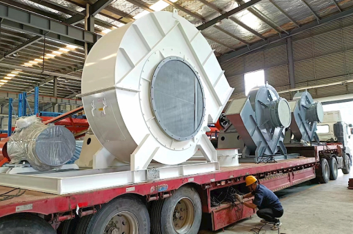
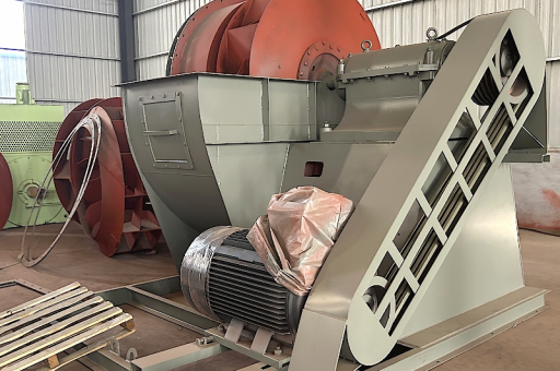
This is an excellent and specific topic. In a thermal power plant, the Induced Draft (ID) fan is one of the largest auxiliary power consumers, often accounting for 20-30% of the total auxiliary power consumption. Its primary job is to pull flue gases through the boiler, economizer, air heater, and precipitator, maintaining a slight negative pressure (draft) in the furnace.
Improving the energy efficiency of an ID fan is a major focus for reducing the plant's Net Operating Heat Rate and lowering operating costs.
Here is a breakdown of the key factors affecting ID fan energy efficiency, along with specific strategies for improvement.
Why ID Fans Are Inefficient (Common Problems)
-
High System Resistance: The flue gas path has significant pressure drops due to:
- Fouling of air pre-heaters (APH) and economizers.
- Clogging of Electrostatic Precipitator (ESP) fields or baghouse filters.
- Ductwork design with sharp bends or undersized dampers.
-
Matching Fan to System: The fan is often oversized.
- Design Margins: Designers add safety margins ("margin on margin") for future load growth, fuel changes, and pressure drops. This results in a fan running far from its Best Efficiency Point (BEP).
- Part-Load Operation: Fans operating at 60-80% capacity run less efficiently, especially if controlled by inlet vanes or dampers.
-
Control Method Inefficiency:
- Inlet Guide Vanes / Dampers: These throttle the flow, creating a pressure drop and wasting energy. They are simple but highly inefficient.
- Variable Speed Drives (VFDs): These are the most efficient, using the "Affinity Laws" (Power ∝ Speed³). A small reduction in speed yields a massive reduction in power.
-
Wear and Tear:
- Erosion: Fly ash erodes impeller blades and casings, reducing aerodynamic performance.
- Rotor Imbalance: Wear and ash buildup cause vibration, increasing frictional losses and requiring more power to maintain flow.
Key Strategies to Improve ID Fan Energy Efficiency
Here are the most effective actions, ranked from high to low impact.
Convert to Variable Speed Drives (VFDs) (Highest Impact)
- The Concept: Replace inlet vane/damper control with a VFD on the motor.
- The Benefit: This is the single most impactful change. For a constant torque application like an ID fan, reducing speed by 20% can reduce power consumption by nearly 50% (0.8³ = 0.51). Payback periods are typically 1-3 years.
- Note: You must check for resonance in the ducting and fan structure at different speeds.
Reduce System Resistance (Operational Optimization)
- Clean Heat Exchangers: Implement a rigorous soot-blowing schedule for the APH and economizer. A clean APH can reduce draft loss by 20-50 mmWC, saving significant fan power.
- Optimize ESP/Baghouse: Maintain proper rapping cycles (ESP) or pulse-jet cleaning (Baghouse) to keep pressure drop low. High pressure drop forces the ID fan to work harder.
- Ductwork Maintenance: Inspect and seal air leaks in the flue gas duct. Air in-leakage increases the volume of gas the fan must handle, directly wasting energy.
Optimize Fan Selection & Sizing (For New or Major Retrofits)
- Avoid Over-Sizing: Use realistic system curves and avoid "margin on margin." A fan designed for the exact operating point will run near its BEP.
- Select High-Efficiency Impellers: Modern backward-curved or airfoil impellers (e.g., BS, BSI types) have higher peak efficiencies (85-90%) than old forward-curved types (60-70%).
- Fan Arrangement: Consider single-inlet vs. double-inlet fans based on space and flow requirements.
Advanced Control Strategies (Software & Automation)
- Fan Pacing: Use a control loop that adjusts the ID fan speed to maintain a precise furnace draft setpoint (e.g., -20 mmWC). Avoid running the fan harder than necessary.
- Two-Fan Optimization: When two ID fans are needed, run both at equal, moderate speeds using VFDs rather than one at full speed and the other throttled. This balances load and efficiency.
- Flow Control via Speed: Always prioritize speed control over vane control for part-load operation.
Preventative Maintenance & Retrofit
- Blade Erosion Protection: Apply hard-facing or ceramic coating to the leading edges of impeller blades to maintain original aerodynamic shape.
- Rotor Balancing & Alignment: Precision balancing minimizes vibration and reduces frictional losses.
- Regular Bearing Maintenance: Proper lubrication reduces friction and motor losses.
- Leakage Reduction: Check and seal any leaks in the fan casing itself.
Energy Efficiency Comparison Table
| Control Method | Typical Efficiency at 100% Flow | Typical Efficiency at 70% Flow | Energy Savings vs. Inlet Vanes (at 70% Flow) |
|---|---|---|---|
| Inlet Vanes / Louvers | 75-80% | 40-55% | Baseline |
| Hydraulic Coupling | 75-80% | 50-60% | ~10-15% better |
| Variable Speed Drive (VFD) | 75-80% | 75-80% | ~30-50% better |
How to Measure & Monitor Efficiency
-
Calculate Fan Power:
Fan Power (kW) = (Flow (m³/s) × Pressure Rise (Pa)) / ( Fan Efficiency (%) × 1000 )Measure actual flow (using pitot tubes or flow meters), pressure (across fan), and motor power. -
Track Specific Power Consumption:
Specific Power (kWh/ton of fuel) = Fan Power (kWh) / Total Fuel Burned (tons)Track this daily. A spike indicates a problem (e.g., APH fouling, damper issue). -
Use a Fan Performance Curve: Plot the actual operating point on the fan’s performance curve. If it's far left (low flow, high pressure drop) or far right (overspeed), efficiency is poor.
Summary & Recommendation
The single most effective action is to retrofit your ID fan with a Variable Frequency Drive (VFD) and run it at the minimum required speed.
Combine this with a disciplined, proactive maintenance program to keep ducts clean, impellers balanced, and bearings lubricated. The combination of a VFD and a low-restriction system will yield the best possible ID fan energy efficiency, directly reducing your plant's operational costs.