
This article's table of contents introduction:
- Table of Contents (Directory Guide)
- Introduction: The Backbone of Industrial Ventilation
- Deep Dive: Exhaust Blower vs. Induced Draught Fan
- Forced Ventilating: The Inlet Side of the Equation
- The Air Filtration System: The Silent Guardian
- System Integration: Design Principles for Maximum ROI
- Frequently Asked Questions (FAQ)
- Conclusion: Future-Proofing Your Facility’s Air Management
** Optimizing Industrial Airflow: The Critical Roles of Exhaust Blower, Induced Draught Fan, Forced Ventilating, and Air Filtration Systems
Table of Contents (Directory Guide)
-
Introduction: The Backbone of Industrial Ventilation
- 1 Defining the Core Components
- 2 Why Integrated Systems Matter for Compliance and Efficiency
-
Deep Dive: Exhaust Blower vs. Induced Draught Fan
- 1 Technical Mechanics of an Exhaust Blower
- 2 The Function of an Induced Draught Fan in Boiler & Process Applications
- 3 Key Differences: Pressure, Placement, and Purpose
-
Forced Ventilating: The Inlet Side of the Equation
- 1 How Forced Ventilation Creates Positive Pressure
- 2 Balancing Act: Interplay with Induced Draft for Optimal Airflow
-
The Air Filtration System: The Silent Guardian
- 1 Filtration Stages: From Pre-filters to HEPA
- 2 Why Filtration Efficiency Directly Impacts Fan Longevity
-
System Integration: Design Principles for Maximum ROI
- 1 Sizing and Matching Fans to Filters
- 2 Energy Optimization Strategies (VFDs and Controls)
-
Frequently Asked Questions (FAQ)
-
Conclusion: Future-Proofing Your Facility’s Air Management
Introduction: The Backbone of Industrial Ventilation
In modern industrial, commercial, and power generation environments, managing air quality and thermal conditions isn’t just a matter of comfort—it is a critical operational and regulatory requirement. At the heart of any serious ventilation strategy lie four interconnected technologies: the Exhaust Blower, the Induced Draught Fan, Forced Ventilating systems, and a robust Air Filtration System. Together, they create a dynamic ecosystem that prevents hazardous gas buildup, controls particulate emissions, maintains temperature gradients, and protects both personnel and machinery.
According to industry best practices and leading engineering resources on fan performance, a common failure point in facility design is treating these units as isolated components. The reality is that an Induced Draught Fan cannot operate optimally if its downstream ductwork is obstructed by an undersized Air Filtration System, nor can an Exhaust Blower maintain its rated flow if the Forced Ventilating supply is mismatched. This article synthesizes engineering handbooks, OEM specifications, and regulatory standards to deliver a comprehensive guide for selecting, integrating, and maintaining these systems.
Deep Dive: Exhaust Blower vs. Induced Draught Fan
1 Technical Mechanics of an Exhaust Blower
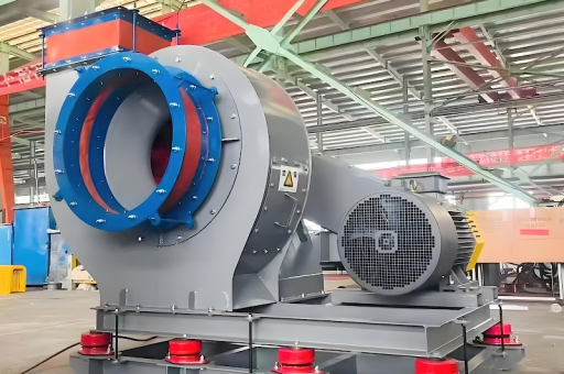
An Exhaust Blower is typically a high-volume, moderate-pressure fan designed to remove air, fumes, or particulates directly from a localized zone or an entire space. It operates by pulling air through an intake and pushing it out through a duct or stack. In fan terminology, this is often categorized as a centrifugal or axial flow system, depending on the required static pressure.
- Common Applications: Spray booths, chemical labs, welding stations, and general bay ventilation.
- Key Spec: Static pressure ratings often range from 0.5” w.g. to 6” w.g. for standard units.
2 The Function of an Induced Draught Fan in Boiler & Process Applications
The Induced Draught Fan (ID Fan) is a specialized subset of the exhaust family, primarily used in thermal power plants, incinerators, and high-temperature process heaters. Its specific role is to exhaust combustion gases (flue gas) by creating a negative pressure (draft) at the furnace exit. This negative pressure ensures that hot gases are drawn safely through the boiler banks, economizers, and ultimately into the stack.
- Critical Distinction: An ID fan often handles hot, abrasive, or corrosive gases. Therefore, its impellers are typically made of wear-resistant alloys and are equipped with cooling systems for the shaft and bearings.
- Performance Metric: ID fans operate at a higher static pressure than standard exhaust blowers, often exceeding 20” w.g., to overcome the resistance of the heat exchangers and scrubbers.
3 Key Differences: Pressure, Placement, and Purpose
While both units remove air, the Exhaust Blower is typically optimized for low-pressure, high-volume applications at ambient or slightly elevated temperatures. In contrast, the Induced Draught Fan is designed for high-temperature, high-pressure scenarios directly tied to combustion efficiency.
| Feature | Exhaust Blower | Induced Draught Fan |
|---|---|---|
| Primary Role | General space or local zone ventilation | Evacuation of furnace combustion gases |
| Temperature Range | Ambient to 150°F (65°C) | 300°F to 750°F+ (150°C to 400°C+) |
| Static Pressure | Low to Medium (0.5 - 6 in. w.g.) | High (10 - 40+ in. w.g.) |
| Material Spec | Standard steel or aluminum | Abrasion-resistant alloys, shaft cooling |
| Control Logic | On/Off or simple VFD | Often tied to furnace master pressure control |
Forced Ventilating: The Inlet Side of the Equation
1 How Forced Ventilation Creates Positive Pressure
Forced Ventilating refers to the mechanical introduction of fresh, outside air into a controlled space. Unlike natural ventilation (which relies on wind or thermal buoyancy), forced systems utilize supply fans—often housed in Air Handling Units (AHUs)—to pressurize a building or a specific zone.
In high-cleanliness environments (e.g., cleanrooms, pharmaceutical plants, data centers), the Forced Ventilating system is meticulously designed to create a slightly positive pressure relative to adjacent spaces. This positive pressure prevents infiltration of unfiltered air from corridors or outdoors, protecting the critical process or equipment from dust and contaminants.
2 Balancing Act: Interplay with Induced Draft for Optimal Airflow
The relationship between Forced Ventilating supply air and the Induced Draught Fan or Exhaust Blower removal is governed by the principle of mass balance.
- If Supply > Exhaust: The space becomes positively pressurized (useful for cleanrooms but may cause door opening difficulties).
- If Exhaust > Supply: The space becomes negatively pressurized (ideal for contamination containment, e.g., asbestos removal).
- If Balanced: The neutral condition, typically favored for general comfort.
Proper design requires that the Forced Ventilating system provides conditioned (heated/cooled/filtered) make-up air to replace the volume being actively removed by the Exhaust Blower. A common industrial error is neglecting make-up air, which starves the Induced Draught Fan, causing cavitation-like effects in ductwork and reduced efficiency.
The Air Filtration System: The Silent Guardian
1 Filtration Stages: From Pre-filters to HEPA
An Air Filtration System serves as the first line of defense for both human health and mechanical equipment. In the context of a fan network, filtration occurs at two critical points:
- Inlet Filtration: Before the Forced Ventilating supply fan. This typically involves MERV 8 pre-filters (for coarse dust and pollen) followed by MERV 13-16 bag filters or high-efficiency HEPA (H14) filters for ultra-clean applications.
- Exhaust Filtration: Before the Exhaust Blower or Induced Draught Fan discharge. For processes generating hazardous dust (e.g., welding fumes, chemical vapors, pharmaceuticals), the Air Filtration System may include:
- Cyclones: For large particulate removal.
- Baghouse Filters: For fine dust collection.
- Scrubbers: For gaseous contaminants.
- HEPA Filters: For sub-micron toxic materials.
2 Why Filtration Efficiency Directly Impacts Fan Longevity
The weakest link in any fan system is the filter. An undersized or dirty Air Filtration System imposes a severe pressure drop on the Induced Draught Fan or Exhaust Blower.
- Increased Load: The fan motor must work harder against the higher resistance, drawing more amperage and generating more heat.
- Reduced Airflow: The actual CFM (Cubic Feet per Minute) delivered drops below design specifications.
- Premature Wear: Solid particles bypassing a failed pre-filter can erode the impeller blades of the Exhaust Blower, leading to imbalance and bearing failure.
Best Practice: Install a differential pressure sensor across the Air Filtration System. When the pressure drop exceeds 1.5x the clean filter rating, an alarm should trigger a cleaning or replacement cycle. This safeguards the expensive fan asset.
System Integration: Design Principles for Maximum ROI
1 Sizing and Matching Fans to Filters
Engineering documents from major fan manufacturers, such as Greenheck and New York Blower, emphasize that a ventilation system must be designed using the System Curve. The combined resistance of the ductwork, dampers, and Air Filtration System must be calculated at the desired CFM. The Induced Draught Fan or Exhaust Blower must then be selected so that its performance curve intersects the system curve at the target operating point.
2 Energy Optimization Strategies (VFDs and Controls)
The most significant operational cost for a Forced Ventilating and Induced Draught Fan system is energy consumption.
- Variable Frequency Drives (VFDs): Installing VFDs on both the supply fan and the Exhaust Blower allows for precise modulation based on demand. A 20% reduction in fan speed reduces energy consumption by approximately 50% (per the Affinity Laws).
- Cascading Control Logic: Link the Induced Draught Fan speed directly to the furnace pressure transmitter. Link the Forced Ventilating fan speed to a room pressure sensor. This closed-loop control minimizes energy waste while maintaining process integrity.
Frequently Asked Questions (FAQ)
Q1: What is the primary difference between an Exhaust Blower and an Induced Draught Fan? A: An Exhaust Blower is a general-purpose fan for removing air from a space or process at ambient temperatures and moderate pressure. An Induced Draught Fan is a specialized, high-temperature, high-pressure fan specifically designed to pull combustion gases out of a boiler or furnace, maintaining a negative furnace pressure for safe operation.
Q2: Can I use an Exhaust Blower as a Forced Ventilating supply fan? A: No, not generally. An Exhaust Blower is designed to discharge against resistance (negative pressure). A Forced Ventilating system requires a supply fan designed to push air (positive pressure) into the space. While some axial fans are reversible, dedicated supply and exhaust units are optimized for their directional flow and pressure characteristics.
Q3: How does the Air Filtration System affect the performance of the Induced Draught Fan? A: The Air Filtration System (e.g., baghouse and scrubber) creates the largest portion of the system pressure drop downstream of the Induced Draught Fan. If the filters become clogged, the ID fan must work against higher resistance, reducing the draft on the furnace and decreasing combustion efficiency. Proper filter maintenance is critical.
Q4: What is "forced ventilating" and why is it necessary? A: Forced Ventilating is the mechanical introduction of fresh air into a building or zone. It is necessary to replace the air being exhausted by industrial fan systems. Without it, the space would be under negative pressure, preventing doors from opening, causing drafts, and starving combustion appliances of oxygen.
Q5: How often should I inspect my Exhaust Blower and Induced Draught Fan? A: A monthly visual inspection for vibration, noise, and debris accumulation is recommended. A comprehensive bearing and belt inspection should be performed quarterly. The fan impeller should be balanced and cleaned annually. The Air Filtration System pressure differential should be monitored continuously via a gauge or transmitter.
Conclusion: Future-Proofing Your Facility’s Air Management
The synergy between the Exhaust Blower, Induced Draught Fan, Forced Ventilating supply, and the Air Filtration System represents the pinnacle of industrial air management. As regulatory bodies like OSHA and the EPA tighten emission and indoor air quality standards, the demand for high-performance, integrated fan systems only grows.
Investing in proper design—using the System Curve for sizing, implementing VFD controls for energy savings, and selecting the correct filtration grade for the application—yields dividends in uptime, compliance, and operational cost reduction. Whether you are designing a new cleanroom, upgrading a boiler house, or retrofitting a paint booth, remember that every component must be harmonized for the system to breathe efficiently.
Final Thought: View your Exhaust Blower and Induced Draught Fan not merely as individual motors and impellers, but as the lungs of your facility. A well-filtered, well-balanced lung system—supported by proper Forced Ventilating—ensures long-term health for both your facility and its occupants.





