
This article's table of contents introduction:
- The Core Specs Decoded
- Application: Kiln Induced Draft (ID) Fan
- Critical Design & Operational Challenges
- Typical Fan Configuration
- Environmental & Regulatory Context
- Common Failure Modes & Maintenance
- Summary for Procurement/Engineering
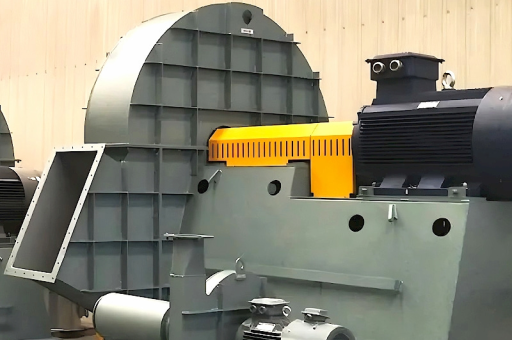
This is a specification for a very large, high-power ID (Induced Draft) fan used in a cement plant's kiln system. Here is a breakdown of what this specification means, the typical application, and key technical considerations.
The Core Specs Decoded
- 700,000 Nm³/hr (Normal Cubic Meters per Hour): This is the volumetric flow rate at "Normal" conditions (0°C, 1.01325 bar). This is a massive flow rate, typical for the main exhaust from a large modern cement kiln (e.g., 5,000–6,000 tons per day clinker production).
- 4,500 kW (Kilowatts): This is the motor power requirement. 4.5 MW is a very large motor (typically 6.6kV or 11kV). This indicates the fan is handling a high pressure drop (likely 70–120 mbar / 700–1200 mmWG) and a high temperature/high dust load.
Application: Kiln Induced Draft (ID) Fan
This fan is specifically the Kiln ID Fan. It is located at the very end of the kiln gas circuit, usually before the stack (chimney).
- Job: It pulls the hot gases through the entire preheater tower (cyclones), the calciner, and the rotary kiln.
- Sucked Through:
- Rotary Kiln
- Preheater / Precalciner
- Raw Mill (if a compound circuit)
- Baghouse / Electrostatic Precipitator (ESP)
- Gas Characteristics:
- Temperature: Typically 150°C to 350°C (depending on location and if in a "mill circuit" or "kiln only" circuit).
- Dust Load: Very high. Can contain 50–100 g/Nm³ of abrasive clinker dust.
- Corrosive Potential: Contains H₂O, CO₂, SOx, NOx, and potentially alkali chlorides.
Critical Design & Operational Challenges
- Dust Erosion (Abrasion): The high dust load is the primary killer of these fans. The impeller and casing must be heavily armored.
- Solution: Wear plates (hardox, cast basalt, ceramic tiles), thick impeller blades (usually backward-curved), and radial blades with replaceable liners.
- Temperature Swings: The fan must handle normal operating temperature (e.g., 250°C) AND upsets (e.g., 400°C flash fires) without seizing or warping.
- Solution: High-temperature alloy (like SA240-316L or 304H), expansion joints in the shaft, water-cooled bearings, and cooling fins on the shaft.
- Rotor Dynamics & Critical Speeds: At 4.5 MW, the rotor is very heavy (several tons). The shaft must be designed to run well below or well above its first critical speed. Operation at a critical speed would cause catastrophic failure.
- Vibration & Balancing: Requires continuous vibration monitoring (accelerometers on bearings) and a high-grade dynamic balancing procedure.
- Variable Speed Drive (VSD): A 4.5 MW fan this size is almost always driven by a variable frequency drive (VFD) or a fluid coupling for soft start and flow control. A direct-on-line starter would blow the power grid. (Drive not included in the 4500kW figure?).
Typical Fan Configuration
| Parameter | Likely Specification |
|---|---|
| Type | Single Inlet, Single Width (SISW) or Double Inlet (DIDW) |
| Orientation | Horizontal shaft (overhung rotor or between-bearings) |
| Impeller | Backward-curved airfoil (for high efficiency at 4500kW) or Backward-inclined with wear protection. |
| Blade Count | 12–16 thick blades |
| Housing | Heavy duty, 10-15mm thick with external stiffening ribs |
| Shaft Seals | Labyrinth seals with purge air (to prevent hot gas leakage to bearings). |
| Bearings | Self-aligning spherical roller bearings with circulating oil lubrication (and a backup grease system). |
| Cooling | Water-cooled bearing housings. |
| Dampers | Variable Inlet Guide Vanes (VIGV) or a large outlet louver damper (for backup/emergency use). |
Environmental & Regulatory Context
- Energy Efficiency: 4500 kW running 24/7 is ~108,000 kWh/day. A poor efficiency fan vs. a 85% efficient one can cost €200,000+ per year in wasted electricity.
- CO₂ Emission: The fan motor's power consumption is a direct source of Scope 2 CO₂ emissions.
- EU BREF / IED: This fan is critical for maintaining proper O₂ levels (typically <6%) in the kiln for NOx control and ensuring proper draft for stable combustion.
Common Failure Modes & Maintenance
- Rotor Imbalance: Due to uneven dust buildup or erosion.
- Bearing Failure: Due to heat soak from the kiln or inadequate cooling.
- Impeller Blade Cracking: Due to high cycle fatigue from resonances or thermal stress.
- Shaft Fretting: At the bearing journal.
- Housing Wear: At the cut-off (scroll tongue).
Summary for Procurement/Engineering
If you are ordering this fan, you need to specify:
- Temperature: Max operating & max design (e.g., 350°C / 450°C).
- Pressure Rise: Static pressure required (e.g., 800 mmWG).
- Material: Casing (e.g., IS 2062 + wear plates) vs. Impeller (e.g., SAILMA 550 or equivalent high-tensile abrasion-resistant steel).
- Speed: (e.g., 1000 RPM or 750 RPM).
- Accessories: Inlet box, inlet guide vanes, shaft seals, expansion joint, dummy baseplate, cooling water connections.
- Drive: VFD / Fluid Coupling / Motor voltage (6.6kV / 11kV).
This is a critical capital asset (often €300,000 - €800,000+) and a plant bottleneck. A failure stops the entire kiln.





