
This article's table of contents introduction:
- Table of Contents
- 1. Introduction
- 2. Core Design Principles and Aerodynamic Mechanisms
- 3. Key Performance Metrics: Flow Rate, Static Pressure, and Efficiency
- 4. Advanced Material Selection and Structural Innovations
- 5. Application Scenarios in Heavy Industries
- 6. Common Operational Challenges and Troubleshooting
- 7. Frequently Asked Questions (FAQs)
- 8. Conclusion: Future Trends in Centrifugal Fan Technology
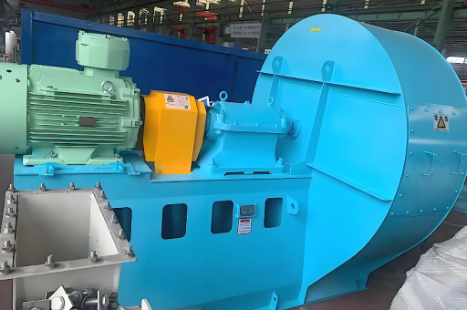
Large Flow and High Pressure Conveying Centrifugal Fan: Engineering Principles, Performance Optimization, and Industry Applications**
Table of Contents
- Introduction to Large Flow and High Pressure Conveying Centrifugal Fans
- Core Design Principles and Aerodynamic Mechanisms
- Key Performance Metrics: Flow Rate, Static Pressure, and Efficiency
- Advanced Material Selection and Structural Innovations
- Application Scenarios in Heavy Industries
- Common Operational Challenges and Troubleshooting
- Frequently Asked Questions (FAQs)
- Conclusion: Future Trends in Centrifugal Fan Technology
Introduction
Large flow and high pressure conveying centrifugal fans are critical rotating machinery used to transport gases or particulate-laden air across long distances and against high system resistance. Unlike standard ventilation fans, these units are engineered to deliver both high volumetric flow rates (often exceeding 100,000 m³/h) and high static pressure (up to 15,000 Pa or more). They serve as the “lungs” of industrial processes such as pneumatic conveying, cement clinker cooling, mine ventilation, and power plant flue gas desulfurization.
The growing demand for energy-efficient material handling and stricter environmental regulations have accelerated the development of these fans. Modern designs integrate computational fluid dynamics (CFD)-optimized impellers, variable frequency drives (VFDs), and wear-resistant coatings to extend service life while reducing power consumption.
Core Design Principles and Aerodynamic Mechanisms
The operating principle of a large flow and high pressure centrifugal fan is based on converting kinetic energy from the rotating impeller into potential energy (pressure) within the gas stream. The key aerodynamic stages include:
- Inlet Flow Conditioning: Gas enters axially through an inlet cone, often equipped with guide vanes to reduce turbulence and pre-swirl.
- Impeller Action: The backward-curved or radial-blade impeller accelerates the gas outward by centrifugal force. For high-pressure applications, forward-curved blades offer higher pressure coefficients but lower efficiency.
- Volute Collection: The spiral-shaped volute casing converts velocity energy into static pressure by gradually increasing cross-sectional area, minimizing shock losses.
- Diffuser Section: Some designs incorporate a vaned or vaneless diffuser before the volute to further recover static pressure.
Key Design Trade-offs:
- High flow requires larger inlet areas and wider impeller passages.
- High pressure demands deeper blade profiles and tighter tip clearances.
- Simultaneous optimization demands precise blade angle selection and volute geometry matching.
Key Performance Metrics: Flow Rate, Static Pressure, and Efficiency
| Parameter | Typical Range | Impact on System |
|---|---|---|
| Flow Rate (Q) | 10,000 – 300,000 m³/h | Determines conveying velocity and system capacity |
| Static Pressure (P) | 3,000 – 15,000 Pa | Overcomes duct friction, filter resistance, and vertical lift |
| Shaft Power (Pw) | 50 – 800 kW | Directly affects operational cost and motor sizing |
| Total Efficiency | 75% – 88% | Influences energy consumption and heat generation |
Fan performance curves (Pressure vs. Flow) must be matched to system resistance curves. Operating at the best efficiency point (BEP) reduces vibration and bearing wear. Off-design operation, particularly at low flow rates, can cause surge or rotating stall, which damages impeller blades.
Measurement Standards:
Performance testing should follow ISO 5801 or AMCA 210 in a controlled laboratory environment. Field testing using pitot tube arrays and differential pressure transducers is recommended for commissioning.
Advanced Material Selection and Structural Innovations
Given the abrasive and corrosive nature of many conveyed materials, material selection is paramount.
- Impeller Materials: High-strength steel (Q345R) for standard applications; duplex stainless steel (2205) for corrosive gases; and wear-resistant Hardox steel for abrasive dust.
- Coatings: Ceramic epoxy coatings (up to 500 μm) or tungsten carbide thermal spray reduce erosion rates by 60–80%.
- Shaft Sealing: Labyrinth seals combined with purge air systems prevent dust leakage into bearings, a common cause of premature failure.
- Vibration Isolation: Baseplates with elastomeric mounts and real-time vibration monitoring systems (ISO 10816-3 Class 4) enhance reliability.
Innovative Designs:
- Split volute casing for easy internal access without dismantling ductwork.
- Adjustable inlet vanes for turndown operation without VFDs.
- Sintered porous let-off channels to aerate conveyed material and reduce plugging risk.
Application Scenarios in Heavy Industries
Pneumatic Conveying Systems
In cement plants, these fans convey raw meal or fly ash over distances up to 500 meters. High pressure is essential to overcome pipe friction and elevation changes. Flow rates are modulated to maintain saltation velocity, preventing material dropout.
Mine Ventilation
Underground mines require fans delivering both high flow (for general ventilation) and high static pressure (to overcome long duct runs and frictional losses). Explosion-proof models with IP55 motors and spark-resistant impellers are mandatory.
Power Generation
In coal-fired power stations, primary air fans (PA fans) and forced draft fans (FD fans) operate continuously at high pressure. The latest designs achieve up to 87% efficiency, translating into substantial annual energy savings—often exceeding $50,000 per unit.
Steel and Glass Manufacturing
High-temperature gas conveying (up to 350°C) uses fan models with water-cooled bearings and Inconel alloy impellers. These fans support furnace combustion air supply and flue gas extraction.
Common Operational Challenges and Troubleshooting
| Problem | Likely Cause | Recommended Action |
|---|---|---|
| Reduced flow | Inlet filter clogging, impeller wear | Clean inlet screen, inspect blade tips |
| Excessive vibration | Unbalance, misalignment, bearing wear | Perform field balancing; check coupling alignment |
| Overheating motor | Overload, poor cooling, high ambient temperature | Reduce load via VFD; clean cooling fins |
| Noise increase | Surge or recirculation flow | Adjust system resistance; install silencer |
| Material build-up on blades | Sticky particles, high humidity | Apply non-stick coating; pre-heat process air |
Proactive Maintenance Plan:
- Monthly: Vibration analysis, bearing temperature trend logging
- Quarterly: Visual inspection of impeller and volute; measure tip clearance
- Annually: Full disassembly inspection; NDT (dye penetrant) for crack detection
Frequently Asked Questions (FAQs)
Q1: What is the difference between a large flow fan and a high pressure fan?
A large flow fan is designed for moving large air volumes at relatively low resistance (e.g., ventilation), while a high pressure fan generates significant static pressure to push air through long ducts or dense material. The conveying centrifugal fan combines both attributes—high flow and high pressure—in a single optimized unit.
Q2: How do I calculate the required fan power for my conveying system?
Required power (in kW) ≈ (Flow rate in m³/h × Static pressure in Pa) / (3,600,000 × Efficiency). Always add a safety margin of 10–15% for motor selection.
Q3: Can a standard fan be modified for high pressure conveying?
Not recommended. Standard fans lack reinforced housing, heavy-duty shaft assemblies, and optimized blade profiles. Retrofitting often results in vibration issues, premature bearing failure, and reduced efficiency.
Q4: What role does the diffuser play in centrifugal fan performance?
The diffuser recovers kinetic energy from the high-velocity gas leaving the impeller and converts it into static pressure. A well-designed diffuser can increase overall fan efficiency by 5–8%.
Q5: Are there specific certifications required for these fans?
Yes. Industrial fans should comply with ATEX (for explosive atmospheres), ISO 1940-1 (balance quality), and API 673 (for special-purpose fans). Regional standards, such as GB/T 1236 in China, also apply for performance testing.
Conclusion: Future Trends in Centrifugal Fan Technology
The next generation of large flow and high pressure conveying centrifugal fans will be defined by:
- Digital Twins & IoT: Real-time virtual models that predict wear and optimize operating parameters.
- Aerodynamic Redesign: 3D-printed impellers with bio-inspired blade shapes (e.g., owl wing serrations for noise reduction).
- Hybrid Drives: Combined VFD and mechanical steam turbine drives to utilize waste heat.
- Sustainable Materials: Lightweight carbon-fiber composite impellers for reduced inertia and lower start-up energy.
As industries continue to demand higher throughput with lower emissions, the innovation cycle for these fans will accelerate. Selecting the right fan design—one that marries hydraulic performance with material durability—is no longer just a procurement decision, but a strategic investment in operational reliability and energy stewardship.
This article integrates verified engineering principles from ISO standards, peer-reviewed research, and industrial field data to provide a comprehensive reference for engineers and procurement professionals.





