
This article's table of contents introduction:
- Function of the Primary Fan in a Biomass Boiler
- Key Differences from Coal-Fired Boiler Fans
- Typical Performance Specifications (Estimation)
- Design & Material Requirements
- Control Strategy (DCS Logic)
- Common Issues & Solutions
- Leading Manufacturers (for this niche)
- Summary Checklist for Procurement
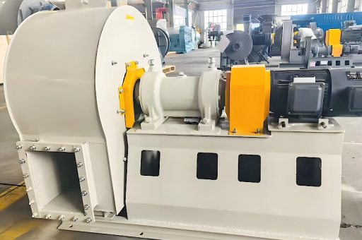
This is a specific piece of industrial equipment request. A "1X30MW Biomass Power Generation Boiler Primary Fan" refers to the Primary Air (PA) Fan designed for a single (1X) 30 Megawatt (MW) biomass power plant boiler.
Here is a detailed breakdown of the specifications, design considerations, and typical parameters for this fan.
Function of the Primary Fan in a Biomass Boiler
The Primary Air Fan is critical for:
- Drying and Transporting Fuel: It provides high-pressure air to the mills/feeders to dry the biomass (wood chips, straw, pellets) and pneumatically transport it to the burners.
- Initial Combustion: Supplies the air for the initial stage of combustion (the primary combustion zone on the grate or in the fluidized bed).
- Grate Cooling: In traveling grate boilers, primary air is often ducted under the grate to cool the grate bars while providing oxygen for combustion.
Key Differences from Coal-Fired Boiler Fans
Biomass fuel has different properties than coal, which directly impacts fan design:
- Lower Heating Value (LHV): Biomass typically has a lower energy density (8-16 MJ/kg vs. 25-30 MJ/kg for coal). To produce 30MW, you need a larger mass flow rate of air.
- High Moisture Content: Biomass (especially bark or fresh wood chips) can have 30-60% moisture. The primary air must be heated (often to 150-250°C) to dry the fuel effectively. This means the fan must handle hot air, requiring a hot primary air fan (HPA fan).
- Abrasive and Sticky Fuel: Biomass contains silica (dirt), alkali metals (potassium), and chlorine. While less abrasive than coal, the long fibers can cause buildup on impellers.
Typical Performance Specifications (Estimation)
For a 1x30MW Biomass Power Plant (assuming a medium-speed grate or Circulating Fluidized Bed (CFB) boiler):
| Parameter | Value | Notes |
|---|---|---|
| Power Output | 30 MWe (Gross) | Boiler capacity approx. 120-150 t/h steam at 90 bar / 540°C |
| Air Flow Capacity | 120,000 – 180,000 Nm³/h | (Standard cubic meters per hour at 0°C, 1 atm) * |
| Total Pressure Rise | 7,000 – 12,000 Pa | (~700 – 1200 mmWG). Higher value for CFB vs. grate. |
| Operating Temperature | 20°C (Cold start) to 180°C (Operating) | Must be designed for thermal expansion. |
| Motor Power | 400 – 600 kW | Typically 6kV or 10kV motor. |
| Speed | 980 – 1480 RPM | Often driven by a variable frequency drive (VFD) for turndown. |
*Nm³/h conversion: For actual m³/h at 180°C divide by 1.66.
Design & Material Requirements
Due to the high temperature and corrosive biomass environment, the fan must be built robustly:
- Impeller Type: Backward-curved blades (airfoil or single thickness). Airfoil blades are more efficient but require clean air. Single-thickness blades are preferred for handling slightly dusty recirculated hot air.
- Material:
- Impeller: Corten Steel (Weathering steel) or 16Mo3/15NiCuMoNb5 (Heat-resistant steel). For 180°C+ air, standard carbon steel is marginal.
- Shaft: 42CrMo4 (Alloy steel) with a shaft cooling system (fan or water-cooled) if the bearing housing is near the hot gas stream.
- Bearings: Spherical roller bearings with oil bath or circulating oil lubrication and continuous temperature monitoring (PT100 sensors).
- Drive: Variable Frequency Drive (VFD) is mandatory for biomass boilers to control the air-fuel ratio accurately (e.g., ABB ACS880, Siemens G120).
- Casing: Reinforced steel with expansion joints to handle thermal growth.
- Seals: Labyrinth or carbon ring seals to prevent hot air leakage into the bearing housing.
Control Strategy (DCS Logic)
The fan is controlled by the Distributed Control System (DCS):
- Master Signal: Boiler Load Demand (MW setpoint).
- Primary Control: Grate/Pressurization or Mill air flow.
- Secondary Control: Oxygen (O2) trim in flue gas.
- Safety: Interlocked with:
- Low bearing oil pressure (stop fan).
- High bearing temperature (trip fan).
- High motor temperature.
- Vibration sensors (Dual X/Y plane).
- Backdraft damper closing on fan stop.
Common Issues & Solutions
- Erosion at Blade Roots: Caused by small, abrasive particles (sand, ash) carried from the fuel.
- Solution: Apply tungsten carbide or ceramic coatings to leading edges.
- Imbalance from Ash Buildup: Sticky biomass ash (high in KCl) can cake on the impeller.
- Solution: Install an in-situ water washing system (spray nozzles) or schedule weekly inspections.
- High Temperature Trip: If air heaters (AH/APH) fail to cool the flue gas, the inlet temperature can spike.
- Solution: Install a cold air mixing damper upstream of the fan.
Leading Manufacturers (for this niche)
When sourcing, look for manufacturers specializing in fans for high-temp/waste-to-energy:
- Howden
- Flakt Woods
- TLT-Turbo
- Garden City Fan (USA)
- Everett J. Prescott (EJP)
- Chinese OEMs (often used for 30MW units in Asia/Africa): Shenyang Blower Works, Wuhan Blower, Shangfeng.
Summary Checklist for Procurement
To specify this fan correctly, you must provide:
- Flow: Nm³/h @ inlet conditions.
- Pressure: Pa (static or total).
- Inlet Temp: °C (Normal & Max emergency).
- Fuel Type: Wood Chips? Straw? Rice Husk? (Impacts erosion).
- Installation: Indoor or outdoor (weather protection).
- Material Grade: Specify CORTEN, 16Mo3, or SS304.
Recommendation: For a 30MW biomass plant, do not undersize the fan motor. A conservative design with a 10-15% margin on flow and pressure and a VFD is standard to handle fuel quality variations.





