This article's table of contents introduction:

- The Context: Why "Coupling Driven" Matters for Balancing
- The Dynamic Balancing Process (Step-by-Step)
- Common Failure Modes & Challenges for Coupling-Driven BC Fans
- Best Practices & Diagnostics
- Standard Specifications (Quick Reference)
- Summary Checklist for a "Coupling Driven Backward Curved Centrifugal Fan Dynamic Balanced"
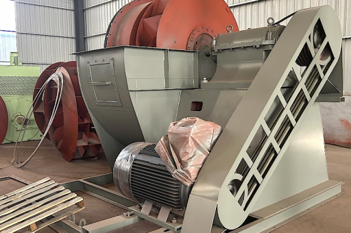
This is a highly specific and technical topic. A Coupling Driven Backward Curved Centrifugal Fan is a common configuration in industrial HVAC, cleanrooms, and material handling. When you add Dynamic Balancing to the equation, you are addressing the most critical factor for the fan's lifespan, noise levels, and bearing reliability.
Here is a comprehensive breakdown of how dynamic balancing applies to this specific fan type, the challenges involved, and best practices.
The Context: Why "Coupling Driven" Matters for Balancing
In a direct-drive fan, the impeller is mounted directly on the motor shaft. In a coupling-driven fan, the impeller is mounted on its own shaft (stub shaft), supported by two bearing pedestals. The motor is connected via a flexible coupling.
The Balancing Implications:
- Isolated Inertia: The motor rotor and the fan impeller are separate masses. They must be balanced independently. The motor is balanced by the manufacturer; the fan assembly (impeller, shaft, sheave/hub) is balanced as a unit.
- Critical Speed: The fan shaft has its own natural frequency. A heavy impeller on a long shaft can have a "critical speed" close to the operating RPM. Dynamic balancing is essential to ensure the fan does not vibrate destructively at its resonance point.
- Coupling Influence: The flexible coupling compensates for minor misalignment but does not correct for unbalance. In fact, a lopsided coupling (due to set screws or keyway fit) can introduce unbalance to the fan system.
The Dynamic Balancing Process (Step-by-Step)
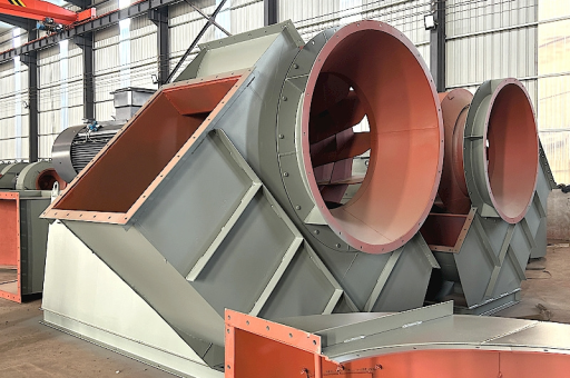
For a backward-curved centrifugal fan, the impeller is the primary source of unbalance. The process follows ISO 1940-1 standards.
Phase 1: Pre-Balance Inspection
- Clean the Impeller: Backward curved blades accumulate dust unevenly. A dirty impeller cannot be balanced accurately.
- Check for Damage: Look for bent blades, erosion, or corrosion. Weld repair is often required before balancing.
- Check the Key: A half-key (longer or shorter than the keyseat) is a classic source of unbalance. The key must fit snugly.
Phase 2: Measurement (Single-Plane vs. Two-Plane)
- Single-Plane (Static Balance): Sufficient for narrow impellers (width < 0.25 x diameter) at low RPM.
- Two-Plane (Dynamic Balance): Mandatory for most industrial backward curved fans.
- Plane 1: Typically at the inlet cone (back plate of impeller).
- Plane 2: Typically at the drive hub (shroud or back plate near the shaft).
- Why two planes? A backward curved impeller is deep. An unbalance on the inlet side creates a couple (wobble) that cannot be corrected by adding weight only at the hub.
Phase 3: Trial Weight & Correction
- Mount the assembly on the balancing machine (or use in-situ balancing equipment).
- Run at operating speed (or a safe lower speed) to measure vibration amplitude and phase.
- Add a trial weight to a known location.
- Re-run to measure the effect.
- Calculate the correction weight (mass) and location (angle).
- Apply correction:
- Add material: Weld a correction weight (usually a steel plate or washer) to the impeller's back plate or shroud.
- Remove material: Grind material off the impeller shroud or back plate (less common on BC fans as it weakens the structure).
Phase 4: Acceptance Criteria (ISO G-2.5 or G-6.3)
- ISO G-2.5: For precision fans (cleanroom, data centers, low noise). Typical target.
- ISO G-6.3: For general industrial fans.
- Vibration Limit: Often specified as < 0.1 inches per second (in/s) or < 2.5 mm/s RMS on the bearing housings.
Common Failure Modes & Challenges for Coupling-Driven BC Fans
This specific setup is prone to several pitfalls that engineers must test for:
| Problem | Cause | Dynamic Balance Symptom |
|---|---|---|
| Coupling Lock-up | The flexible element (spider or disc pack) fails, causing the coupling to become rigid. | Vibration spikes once per revolution (1x RPM). The fan shaft is now fighting the motor shaft. |
| Keyway Fit | The key is loose in the shaft or hub keyway. | Unpredictable vibration; unbalance changes each time the fan is started. |
| Bearing Fit | The bearing is loose on the shaft or tight in the housing. | Vibration may appear as sub-harmonic (0.5x RPM) or shift over time. |
| Resonance | The fan assembly's natural frequency matches running speed. | High vibration that does not reduce after dynamic balancing. (Requires structural modification). |
| Thermal Growth | The fan runs hot (e.g., in a dryer). The shaft expands, pushing the impeller away from the inlet. | Unbalance appears only at operating temperature (cold balance is off). |
Best Practices & Diagnostics
If you are commissioning or troubleshooting a vibration issue on a coupling-driven BC fan:
Check Alignment FIRST
- Never balance a fan that is misaligned. Misalignment causes vibration at 1x RPM (just like unbalance) and 2x RPM.
- Use a laser alignment tool on the motor coupling hubs.
Isolate the Source
- Run the motor uncoupled: If the motor vibrates alone, balance the motor.
- Bump test the fan: Give the fan a quick start and coast down. Look for a spike in vibration at a specific RPM (critical speed). Do not run at that speed.
In-Situ Balancing (The Field Fix)
- If the fan is too large to remove, use a portable vibration analyzer with a tachometer.
- Apply trial weights to the impeller shroud (inlet side) or on the hub (drive side) using magnetic clamps (temporary) or weld weights (permanent).
Key Factors for Backward Curved Blades (BC)
- High Inlet Velocity: Uneven flow at the inlet can excite the blades. A poorly designed inlet cone can cause aerodynamic instability that looks like unbalance.
- Thin Blades: BC blades are often sheet metal. Welding a correction weight in the wrong place can warp the blade, creating more unbalance.
Standard Specifications (Quick Reference)
- Residual Unbalance:
- ( U_{per} = (9549 \times G \times M) / N )
- Where: ( U_{per} ) = permissible residual unbalance (g·mm), ( G ) = balance grade (e.g., 2.5), ( M ) = rotor mass (kg), ( N ) = RPM.
- Vibration Velocity (ISO 10816-3):
- Good: < 1.8 mm/s RMS
- Acceptable: < 4.5 mm/s RMS
- Unsatisfactory: > 7.1 mm/s RMS (Requires balancing)
Summary Checklist for a "Coupling Driven Backward Curved Centrifugal Fan Dynamic Balanced"
- ✅ Impeller is clean and structurally sound.
- ✅ Keyway slots are filled with a key of exact length (no protruding ends).
- ✅ Coupling is aligned to within 0.002" (0.05 mm) angular and parallel.
- ✅ Two-plane dynamic balance performed to ISO G-2.5.
- ✅ Vibration measured at both bearing housings (Horizontal, Vertical, Axial).
- ✅ Vibration velocity is below the specified limit (e.g., < 2.5 mm/s RMS).
Final Note: If you encounter "Coupling Driven Backward Curved Centrifugal Fan Dynamic Balanced" in a technical document or RFP, it means the vendor is required to provide a certified trim balance (after installation) to ensure the fan runs smoothly at its operating point. This is a sign of a high-quality installation.