This article's table of contents introduction:

- The Critical Material Challenge (The Impeller & Shaft)
- Housing and Structure
- Bearing and Lubrication (The Achilles Heel)
- Drive System (Motor vs. Turbine)
- Design Configurations (Which type?)
- Specific Applications for a 1050°C Fan
- Critical Operational Risks
- Summary Specifications for a Custom Build
- Important Warning
This is a highly specialized piece of industrial equipment. A fan capable of handling flue gas at a continuous temperature of 1050°C (1922°F) is at the extreme upper limit of current mechanical engineering. Standard high-temperature fans stop around 600-850°C. To achieve 1050°C, you cannot simply use "heat-resistant steel"; you must use superalloys or ceramic-based designs.
Here is the technical breakdown of how this fan must be designed, constructed, and specified.
The Critical Material Challenge (The Impeller & Shaft)
At 1050°C, standard stainless steel (304, 310) loses all mechanical strength and will sag or melt. You need:
- Nickel-Based Superalloys: Materials like Inconel 718, Hastelloy X, or Haynes 230. These maintain tensile strength and creep resistance up to 1100°C.
- Inlet Gas Cooling (Critical): Even with superalloys, the shaft and bearings cannot survive 1050°C. The fan MUST have a cooling system:
- Cooling Disk (Radiation Shield): A metal disc attached to the shaft between the impeller and the bearing housing to block radiant heat.
- Forced Air Cooling: A secondary fan blows ambient air over the shaft and into the bearing housing.
- Shaft Material: Often a lower-alloy steel (e.g., 42CrMo4) for strength, but it is completely isolated from the hot gas by the cooling system.
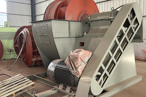
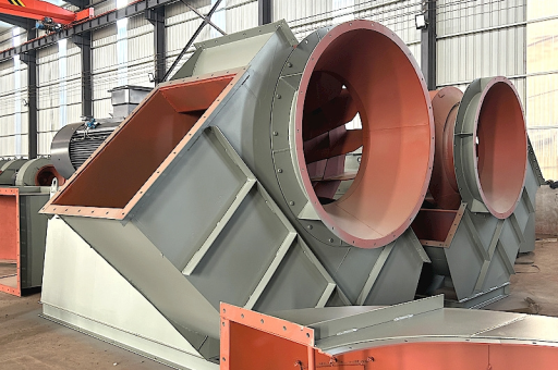
Housing and Structure
- Refractory Lining: The fan housing (casing) is typically made of carbon steel (for strength) but is internally lined with castable refractory ceramic (e.g., Alumina-based) of 100-150mm thickness. The steel shell never sees the 1050°C.
- Expansion Joints: The housing must have massive bellows (Inconel or ceramic fiber) to handle thermal expansion of the ductwork.
- Stand/Base: Must be water-cooled or heavily finned to prevent heat transfer to the foundation.
Bearing and Lubrication (The Achilles Heel)
Bearings fail instantly at 1050°C. They must be kept below 80°C.
- Isolation:
- Long Shaft Spacer: A 500mm-1000mm extension between the impeller and the bearing housing.
- Water-Cooled Jacket: A water jacket around the shaft at the bearing housing entry.
- Bearing Type:
- Water-Cooled Sleeve Bearings: Common for extreme continuous duty.
- High-Temp Grease Bearings: Only if the cooling system is flawless (rarely used at this temp).
- Monitoring: Mandatory vibration probes and temperature sensors (PT100) on all bearing housings with automatic shut-off.
Drive System (Motor vs. Turbine)
A standard electric motor cannot be mounted directly to the fan.
- Motor Placement: The motor must be mounted on a separate, isolated base, connected via a heat-shedding long coupling.
- Variable Speed Drive (VFD): Essential for controlling flow without using dampers (which would melt in the gas stream).
- Alternative: In some refinery/cement applications, a steam turbine or hydraulic motor is used to avoid electrical components near extreme heat.
Design Configurations (Which type?)
- Radial (Centrifugal) Fan: The only viable option. Usually with Backward Curved Blades or Radial Tipped Blades. Forward curved blades are too fragile.
- Single or Double Inlet? Double inlet (high flow) is possible but the shaft support becomes very complex due to heat.
- Overhung vs. Between-Bearing:
- Overhung (Cantilevered): Best for thermal expansion. The impeller hangs on one end of the shaft, allowing the shaft to expand freely. Most common for 1050°C.
- Between-Bearing (Center Hung): Used for massive fans but requires very complex sliding bearing supports to handle expansion.
Specific Applications for a 1050°C Fan
You are likely dealing with one of these processes:
- Cement Kiln Exhaust Gas: After the preheater tower (raw meal preheating).
- Waste Incineration: After the secondary combustion chamber (post-combustion zone).
- Glass Furnace Exhaust: Highly corrosive (alkali/boron) + 1050°C.
- Metallurgy (EAF / Converters): Off-gas handling from steelmaking (often with explosive gas mixes).
Critical Operational Risks
- Thermal Shock: The fan must be pre-heated slowly (ramp rate < 50°C/hour). Cold ambient air hitting the 1050°C impeller will cause immediate cracking of superalloys.
- Creep Fatigue: The impeller blades will slowly deform over time (creep). You must calculate a design life (e.g., 10,000 hours) and replace the impeller based on mandated life limits, not failure.
- Corrosion: At 1050°C, chlorine (from waste) or vanadium (from heavy oil) will attack even superalloys. Specify coating (e.g., Aluminum diffusion coating) or a higher alloy (e.g., HR-120).
Summary Specifications for a Custom Build
If you are procuring this fan, your spec sheet must include:
| Parameter | Requirement |
|---|---|
| Gas Temperature | 1050°C (Continuous) |
| Max Peak Temp | 1100°C (Transient, <1 hour) |
| Impeller Material | Inconel 718 or Haynes 230 |
| Shaft Cooling | Forced air + Radiation Disk + Water Jacket |
| Housing Lining | 125mm Castable Alumina Refractory (65% Al2O3) |
| Bearings | Water-cooled Sleeve or Oil Mist |
| Motor Base | Isolated (heat shed) with long shaft coupling |
| Thermal Expansion | Axial compensation > 20mm |
| Life Expectancy | Impeller: 12,000 hours (mandatory replacement) |
Important Warning
Standard high-temperature fans (labeled "1000°C") sold by many vendors often only survive that temperature for a few minutes of peak surge or utilize a dilution air system (mixing cold air to drop gas temp). A true 1050°C continuous-duty fan is a bespoke, extremely expensive machine (often > $200,000 USD) requiring CAD/FEA analysis for thermal stress. You cannot buy this off-the-shelf.
Would you like me to provide a technical diagram of the cooling system or suggest specific OEM manufacturers that specialize in this niche (e.g., TLT-Babcock, Greenheck Industrial, Howden)?