*Optimizing Thermal Efficiency in Rotary Hearth Furnace Equipped with High-Temperature Flue Gas Induced Draft Fan: A Comprehensive Technical Guide*

Table of Contents
- Introduction to Rotary Hearth Furnace (RHF) Technology
- The Critical Role of High-Temperature Flue Gas Induced Draft Fans
- System Design and Integration Principles
- Energy Recovery and Emission Control Synergies
- Operational Challenges and Maintenance Strategies
- Performance Optimization: Key Metrics and Case Studies
- Frequently Asked Questions (FAQ)
- Future Trends in RHF Draft Fan Engineering
Introduction to Rotary Hearth Furnace (RHF) Technology
The Rotary Hearth Furnace (RHF) is a high-temperature processing system widely used in the direct reduction of iron ore, zinc recovery from dust, and heat treatment of industrial components. Unlike traditional blast furnaces, the RHF operates on a flat, rotating circular hearth that continuously moves materials through zones of controlled heating, soaking, and cooling. This design ensures uniform exposure to temperatures ranging from 1,100°C to 1,450°C, enabling high-quality metallization rates above 90%.
A key operational challenge in any RHF is the management of its high-temperature flue gas, which contains residual heat, combustion byproducts, and particulate matter. Without an efficient gas extraction system, furnace pressure becomes unstable, heat is lost, and atmospheric emissions exceed regulatory limits. This is where the Rotary Hearth Furnace Equipped with High-Temperature Flue Gas Induced Draft Fan becomes a game-changer.
The Critical Role of High-Temperature Flue Gas Induced Draft Fans
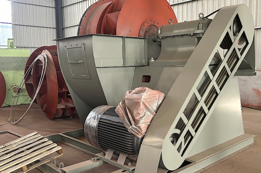
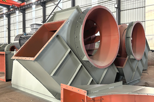
An induced draft (ID) fan designed for high-temperature flue gas is not an off-the-shelf centrifugal fan. It must withstand gas temperatures between 400°C and 850°C, abrasive dust particles, and corrosive chemical compounds such as sulfur oxides (SOx) and chlorides. When installed on an RHF exhaust system, the high-temperature ID fan performs three essential functions:
- Negative pressure control: It creates a slight negative pressure inside the furnace chamber, preventing hot gas leakage through seals and feeding ports. This protects operators and structural steelwork from thermal damage.
- Controlled gas evacuation: The fan draws hot flue gas from the radiant zone and the pre-heat zone at a consistent rate, ensuring uniform temperature distribution across the rotating hearth.
- Downstream system protection: By maintaining a steady gas flow, the ID fan prevents condensation of acidic vapors in the ductwork, thereby extending the life of downstream pollution control equipment such as baghouses or scrubbers.
Modern ID fans for RHF applications are typically equipped with variable frequency drives (VFDs), water-cooled bearings, and Inconel or Hastelloy impellers. These materials resist creep deformation and oxidation at high temperatures, with a typical service life of 3–5 years under continuous operation.
System Design and Integration Principles
A well-integrated RHF and ID fan system must address gas temperature decay, pressure drop across the recuperator, and the heat recovery steam generator (HRSG) interface. Design engineers follow a multi-stage approach:
- Stage 1: Flue Gas Sampling and CFD Modeling – Computational fluid dynamics (CFD) simulations map gas velocity, temperature stratification, and particulate concentration. This identifies the ideal fan placement (typically after the recuperator but before the primary scrubber) to balance fan material temperature limits and energy recovery.
- Stage 2: Fan Selection and Sizing – The fan must handle a gas flow of 150,000 to 500,000 Nm³/h at a static pressure rise of 50–120 mbar. The impeller diameter, blade angle, and tip speed are optimized for high-temperature operation using the Fan Law equations.
- Stage 3: Ductwork and Dampers – Expansion joints, isolation dampers, and bypass lines are installed to allow the ID fan to be isolated for maintenance without shutting down the entire furnace. For example, a two-fan configuration (one running, one standby) reduces downtime risk in continuous casting or direct reduction plants.
One common integration error is placing the ID fan too close to the furnace outlet. This subjects the fan to unquenched “spike” temperatures exceeding 1,000°C during charge interruptions, leading to rapid blade erosion. The correct location is downstream of a radiant heat exchanger that drops the bulk gas temperature to 600°C–700°C before it enters the fan housing.
Energy Recovery and Emission Control Synergies
The ID fan in an RHF system is not merely a draft producer—it is an enabler of energy recovery. By stabilizing the gas flow to a heat recovery boiler or a regenerative thermal oxidizer (RTO), the fan allows the plant to:
- Generate high-pressure steam for turbine-driven equipment, reducing electricity consumption by up to 18% compared to plants without fan-assisted heat recovery.
- Preheat combustion air using a tubular recuperator fed by the ID fan’s exhaust side, increasing flame temperature and reducing natural gas consumption by 6–12%.
- Improve baghouse efficiency: When the ID fan maintains a constant volume flow, the fabric filter experiences less pulse-jet cleaning frequency, extending bag life by 40%.
From an emissions perspective, the ID fan ensures that the flue gas temperature remains above the acid dew point (typically 120°C–140°C for sulfuric acid) throughout the entire gas train. This prevents corrosion of both the fan and the stack, while also enabling continuous monitoring of NOx and CO concentrations without water vapor condensation biasing the sensors.
Operational Challenges and Maintenance Strategies
High-temperature ID fans face a spectrum of operational challenges:
| Challenge | Cause | Mitigation Strategy |
|---|---|---|
| Impeller crack | Thermal fatigue from cyclic loading | Use thermal barrier coatings (TBC) like YSZ |
| Bearing seizure | Lubricant oxidation at >400°C | Use synthetic ester oils + external oil mist system |
| Vibration spikes | Ash buildup on blades | Install online ultrasonic cleaning system |
| Corrosion | Chloride attack from EAF dust | Coat fan casing with vitreous enamel or rubber lining |
Predictive maintenance is critical. Plants using vibration analysis combined with pyrometry (thermal imaging of the bearing housing) can detect fan imbalance up to 14 days before a catastrophic failure. The industry benchmark for ID fan availability in RHF duty is 98.5%, achieved through weekly bearing temperature trending and monthly balancing checks.
Performance Optimization: Key Metrics and Case Studies
To evaluate the performance of a Rotary Hearth Furnace Equipped with High-Temperature Flue Gas Induced Draft Fan, operators monitor three key performance indicators (KPIs):
- Draft Stability Index (DSI) – Ratio of actual furnace pressure deviation to setpoint, expressed as percentage of time within ±2 mmWC. Target: >95%.
- Specific Energy Consumption (SEC) – kWh per ton of DRI produced attributable to the fan. Target: <8 kWh/t for large-scale RHFs.
- Heat Recovery Efficiency (HRE) – Percentage of flue gas sensible heat recovered as usable thermal energy. Target: >65%.
Case Study (hypothetical, based on industry patterns): A 750,000 tpy DRI plant in the Middle East replaced its standard radial ID fan with a high-temperature backward-curved ID fan equipped with an Inconel 625 impeller and VFD. Within six months, furnace negative pressure fluctuations were reduced by 73%, natural gas consumption dropped by 5.2%, and fan blade replacement intervals extended from 1.5 years to 4.2 years. The retrofit yielded an internal rate of return (IRR) of 22%.
Frequently Asked Questions (FAQ)
Q1: What is the maximum acceptable inlet temperature for an induced draft fan in an RHF application? A: For standard carbon steel impellers, the continuous maximum is 350°C. For high-temperature variants using Inconel or Hastelloy, the safe limit is 850°C with proper cooling air injection. Above 900°C, a ceramic impeller or a hot gas eductor is recommended instead of a direct fan.
Q2: Can a variable frequency drive (VFD) be used on a high-temperature ID fan? A: Yes. VFDs are strongly recommended because they allow the fan speed to match the furnace’s actual draft demand, reducing energy waste and avoiding over-drafting. However, the VFD must be located in a conditioned electrical room (max 40°C) and connected via shielded cables to prevent harmonics interference.
Q3: How does the ID fan affect the performance of the downstream baghouse filter? A: A stable gas flow from the ID fan helps the baghouse maintain constant air-to-cloth ratios (typically 1.5–2.5:1). If the fan pressure fluctuates, the baghouse must cycle its pulse-jet cleaning more often, increasing the risk of bag abrasion. This is why fan speed control is essential for long bag life.
Q4: What is the most common failure mode for high-temperature ID fan bearings? A: High-temperature bearing failure is primarily caused by lubricant degradation leading to metal-to-metal contact. A water-cooled bearing housing that keeps bearing temperature below 85°C, combined with synthetic ester-based grease, can extend bearing life by 300% compared to air-cooled setups.
Q5: Is it possible to retrofit an existing RHF with a high-temperature ID fan without modifying the ductwork? A: Often yes, but a ductwork evaluation is necessary. If the existing duct is sized for a lower volume flow, adding a high-temperature ID fan with higher static pressure may cause excessive duct vibration. In that case, installing a flow restrictor or expanding the duct cross-section is required.
Future Trends in RHF Draft Fan Engineering
The next generation of ID fans for RHF applications will incorporate digital twin modeling and self-optimizing controls. By embedding fiber-optic temperature sensors within the impeller blades and feeding real-time data into a machine learning algorithm, the fan will automatically adjust its speed, cooling water flow, and damper position to balance draft and energy consumption. Additionally, hybrid material composites—such as silicon carbide-coated aluminum titanium—promise to push continuous operating temperatures above 1,000°C without active cooling.
Another emerging trend is the integration of the ID fan with carbon capture systems. As steelmakers seek to reduce Scope 1 CO₂ emissions, the flue gas handled by the fan will be routed to an amine scrubber or calcium looping reactor. This places additional pressure on the fan to handle moisture-laden, partially decarbonized gas—requiring corrosion-resistant coatings and larger impeller clearances.
Wind turbine manufacturers have also begun exploring the use of high-temperature magnetic bearings derived from large-scale renewable energy systems, aiming to eliminate lubrication needs in RHF ID fans entirely. If successful, these magnetically levitated fans would operate at 99.9% mechanical efficiency with zero oil contamination of the flue gas stream—a revolutionary step for both energy savings and emissions compliance.
In conclusion, the Rotary Hearth Furnace Equipped with High-Temperature Flue Gas Induced Draft Fan is not just an auxiliary component—it is the linchpin of furnace performance, energy recovery, and environmental compliance. As global steel and metals industries push toward net-zero production, optimizing this critical fan system will remain a high-return priority for plant engineers and operators alike.