
** Optimizing Cement Production: The Critical Role of Centrifugal Boiler ID Fan and Induced Draft Blower Systems
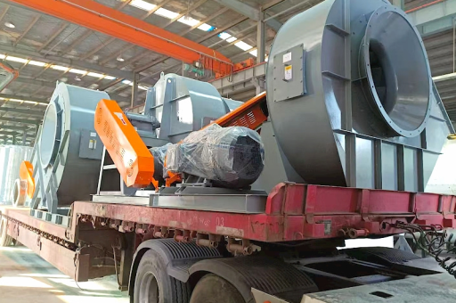
Table of Contents
- Introduction: The Heart of Cement Plant Airflow Management
- Understanding the Centrifugal Boiler ID Fan in Cement Kilns
- Induced Draft Blower: Function, Design, and Operational Principles
- Key Differences Between ID Fans and Forced Draft Fans in Cement Lines
- Material and Engineering Considerations for High-Temperature, Abrasive Environments
- Common Failure Modes: Vibration, Erosion, and Bearing Wear
- Efficiency Optimization: Variable Frequency Drives and Blade Geometry
- Maintenance Strategies for Extended Fan Life in Cement Plants
- Q&A: Expert Answers on ID Fan Selection and Troubleshooting
- Conclusion: Ensuring Reliable, Energy-Efficient Airflow for Cement Manufacturing
Introduction: The Heart of Cement Plant Airflow Management
In the cement industry, the Centrifugal Boiler Id Fan Induced Draft Blower For Cement Industry represents a cornerstone of thermal and mechanical process efficiency. Cement manufacturing is heavily reliant on precisely controlled gas flows: from preheating raw meal in the preheater tower to calcining in the kiln and cooling clinker in the grate cooler. Every combustion and heat exchange step requires a robust, high-temperature induced draft (ID) fan system to pull flue gases through the equipment and maintain negative pressure.
A centrifugal boiler ID fan, specifically engineered for induced draft service, handles large volumes of dusty, corrosive, and hot gases (often exceeding 350°C). Unlike forced draft fans that push air into the system, the induced draft blower creates a vacuum at the outlet of the kiln or boiler, ensuring complete combustion and preventing backflow of hazardous gases. For cement plant operators, selecting the correct ID fan is not merely a technical decision—it directly impacts fuel consumption, clinker quality, and emission compliance.
This article provides a comprehensive, SEO-optimized guide to the design, operation, maintenance, and troubleshooting of centrifugal boiler ID fans and induced draft blowers within the cement context, drawing from industry best practices and engineering standards.
Understanding the Centrifugal Boiler ID Fan in Cement Kilns
The term Centrifugal Boiler Id Fan Induced Draft Blower For Cement Industry encompasses a specialized rotating machine that moves hot, particle-laden gases through the kiln system. In a typical cement plant, the ID fan is located after the baghouse or electrostatic precipitator, pulling gases from the kiln, preheater, and calciner through the pollution control equipment before discharging to the stack.
- Operating Principle: An ID fan uses a rotating impeller to accelerate gas radially outward, converting kinetic energy into static pressure. The fan inlet is connected to the ductwork from the precipitator, while the outlet discharges to the chimney. The negative pressure created by the fan prevents fugitive emissions and maintains proper airflow for combustion.
- Design Features for Cement Service:
- High-temperature bearings and cooling system: To withstand gas temperatures up to 400°C, fans often incorporate water- or air-cooled bearing housings.
- Abrasion-resistant impeller materials: Hard-faced wear plates or ceramic coatings protect against dust erosion.
- Radial or backward-inclined blades: Backward-bladed designs offer higher efficiency and lower noise, but radial blade fans are more tolerant of dust buildup.
- Performance Parameters: Flow rate (m³/h), static pressure (Pa), and fan speed (RPM) are selected to match the plant’s specific gas volume and resistance. Efficiency typically ranges from 75% to 85% for modern centrifugal designs.
A poorly performing ID fan leads to reduced kiln production, increased fuel consumption, and frequent unplanned shutdowns. Therefore, understanding the fan’s role in the heat balance is critical.
Induced Draft Blower: Function, Design, and Operational Principles
An Induced Draft Blower in a cement plant is synonymous with the ID fan, but the term “blower” sometimes implies a higher-pressure, lower-volume unit. However, for large cement kilns, the induced draft blower must move enormous volumes—often exceeding 500,000 m³/h.
- How It Works: The induced draft blower creates a pressure differential (negative gauge pressure) at its inlet. This suction pulls combustion gases through the preheater cyclones, the kiln, and the cooler, ensuring that hot gases travel in the desired direction. The blower’s discharge is typically at atmospheric pressure or slightly positive, depending on stack height.
- Critical Design Considerations for Cement:
- Gas composition: High CO₂ content, water vapor, and SO₂ require corrosion-resistant alloys for fan casings and impellers.
- Temperature variation: Kiln startups and upsets can cause rapid temperature fluctuations; fans must have thermal expansion compensation.
- Dust loading: Even after a baghouse, residual dust erodes blades; hardened blade edges or sacrificial wear strips are common.
- Control Strategies: Most modern induced draft blowers are driven by variable frequency drives (VFDs) . By modulating motor speed, VFDs adjust fan flow to match process demand, saving 15%–30% energy compared to damper control.
An induced draft blower must also comply with environmental regulations. As emission standards tighten, the fan’s ability to maintain constant negative pressure under varying loads becomes essential for filter performance.
Key Differences Between ID Fans and Forced Draft Fans in Cement Lines
To fully grasp the Centrifugal Boiler Id Fan Induced Draft Blower For Cement Industry application, it is helpful to contrast it with forced draft (FD) fans:
| Feature | Induced Draft (ID) Fan | Forced Draft (FD) Fan |
|---|---|---|
| Location | After the process (kiln/precipitator) | Before the process (burner inlet) |
| Gas conditions | Hot, dusty, corrosive | Clean, ambient air |
| Pressure | Negative (suction side) | Positive (discharge side) |
| Blade type | Often radial or backward-inclined | Usually airfoil or forward-curved |
| Material | Abrasion-resistant alloy | Standard carbon steel |
| Purpose | Extract flue gases | Supply combustion air |
In cement plants, the combination of FD and ID fans balances the kiln system. If the ID fan fails, pressure in the kiln becomes positive, forcing hot gases out of openings and endangering personnel. Conversely, an FD fan failure starves the burner of oxygen.
Understanding these differences helps engineers specify the correct centrifugal boiler ID fan for their specific boiler or kiln circuit.
Material and Engineering Considerations for High-Temperature, Abrasive Environments
The Centrifugal Boiler Id Fan Induced Draft Blower For Cement Industry must survive extreme conditions:
- High Temperature: Gas temperatures in the boiler or kiln exit can exceed 400°C. Fan impellers may be made of 13% chromium stainless steel (e.g., AISI 410) or duplex stainless steel for higher strength at temperature. Shaft materials require thermal expansion allowances.
- Abrasive Particulates: Cement dust contains silica and lime, which act as grinding media. Hardfacing on impeller blade leading edges, use of ceramic tiles on wear zones, and replaceable wear plates in the casing extend fan life from months to years.
- Corrosion: Acid condensation (from SO₃ and H₂O) can attack fan internals. In cold climates, fans must be insulated or equipped with trace heating to prevent corrosion during shutdown.
Engineering also focuses on rotor dynamics: fans must operate below the first critical speed to avoid resonance. Balancing to ISO G2.5 or better is standard for large cement ID fans.
Common Failure Modes: Vibration, Erosion, and Bearing Wear
Despite robust design, Centrifugal Boiler Id Fan Induced Draft Blower For Cement Industry systems experience predictable issues:
- Vibration from Imbalance: Uneven dust deposition on blades or erosion causes mass imbalance. Vibration amplitude >7 mm/s suggests immediate inspection.
- Blade Erosion: Leading edge thinning reduces efficiency. Regular thickness checks (ultrasonic) every six months are recommended.
- Bearing Failure: High temperature and vibration degrade grease or oil. Premature bearing failure often results from inadequate cooling or misalignment.
- Shaft Crack Propagation: Thermal cycling can initiate fatigue cracks at keyway or fillet radii. Non-destructive testing (MPI) during overhauls prevents catastrophic failures.
- Corrosion at Inlet Box: Acid condensation attacks inlet guide vanes and ductwork.
Proactive monitoring (online vibration, temperature, and current trending) reduces unplanned downtime.
Efficiency Optimization: Variable Frequency Drives and Blade Geometry
Modern Induced Draft Blower systems in cement plants are optimized for efficiency:
- Variable Frequency Drive (VFD): Replaces inefficient inlet dampers. By reducing fan speed from 100% to 80%, motor power drops by half (cube-law relationship). Energy savings often pay back the VFD investment within 18 months.
- Blade Geometry Selection: Backward-inclined blades provide higher aerodynamic efficiency (up to 85%) but handle dust less well. For high-dust applications, radial or radial-tip blades are preferred despite lower efficiency. Computational fluid dynamics (CFD) is used to model flow patterns and minimize recirculation.
- Inlet Guide Vanes (IGVs): When VFDs are not feasible, IGVs adjust pre-swirl to match flow demand, offering 10%–15% energy savings over outlet dampers.
Combining VFDs with proper blade selection can yield 20%–30% energy savings, directly reducing the plant’s carbon footprint.
Maintenance Strategies for Extended Fan Life in Cement Plants
A structured maintenance plan for the Centrifugal Boiler Id Fan Induced Draft Blower For Cement Industry includes:
- Weekly: Check motor current, bearing temperature, vibration readings, and oil levels.
- Monthly: Inspect inlet box for dust buildup; clean or replace filter screens.
- Quarterly: Perform laser alignment between motor and fan; check belt tension (if belt-driven).
- Annually: Conduct full bore scope inspection of impeller; measure blade thickness; replace wear plates.
- Overhaul (3–5 years): Balance rotor; replace bearings; inspect shaft for cracks; recoat internal surfaces.
Advanced condition monitoring using accelerometers and thermography enables predictive maintenance. Cement plants that adopt such programs report fan life extending from 4 to 8 years between major overhauls.
Q&A: Expert Answers on ID Fan Selection and Troubleshooting
Q1: How do I select the correct Centrifugal Boiler ID Fan for my cement kiln?
A: First, determine the required flow rate (m³/h) and system resistance (static pressure, Pa) at full load. Factor in gas density (due to temperature). Choose a fan with a performance curve that shows stable operation near the design point. Select backward-inclined blades for clean gas, radial blades for dusty gas. Specify abrasion-resistant materials and include a VFD for flexibility. Always consult the fan manufacturer’s selection software.
Q2: My ID fan vibrates excessively after a kiln restart. What should I do?
A: Shut down the fan and inspect for dust accumulation on blades. Uneven deposit loss during startup causes imbalance. Clean blades manually or using compressed air. Also check if bearings were damaged during the temperature transient. If vibration persists, rebalance the rotor on site.
Q3: Can I retrofit my existing induced draft blower with a VFD?
A: Yes, but verify motor insulation rating (Class F or H required for VFD operation). Check if the fan’s critical speed range could be excited by the VFD’s variable frequency. Install a sine-wave filter if motor bearing currents are a concern. Retrofit payback is typically 1–2 years in cement plants.
Q4: What causes premature bearing failure in cement ID fans?
A: Common causes include: (1) inadequate cooling water flow to bearing housings, (2) misalignment between motor and fan, (3) contamination of grease by dust ingress, and (4) operation above rated temperature. Implement a condition monitoring program to detect early degradation.
Q5: How does the induced draft blower affect clinker quality?
A: Proper ID fan operation maintains the correct negative pressure in the kiln, ensuring stable flame shape and complete combustion. Insufficient draft leads to reducing conditions in the burning zone, which can cause clinker quality issues such as free lime variability or color change.
Conclusion: Ensuring Reliable, Energy-Efficient Airflow for Cement Manufacturing
The Centrifugal Boiler Id Fan Induced Draft Blower For Cement Industry is not merely a component—it is a critical enabler of the entire cement production process. From pulling hot gases through the preheater to maintaining emission compliance, the ID fan’s reliability directly correlates with plant uptime, energy consumption, and product quality.
By understanding the differences between induced draft and forced draft systems, selecting appropriate materials for high-temperature/abrasive service, implementing VFD-based optimization, and adopting proactive maintenance strategies, cement plants can dramatically improve fan performance. Engineers and operators must remain vigilant about vibration, erosion, and thermal management to avoid costly failures.
As the cement industry moves toward carbon neutrality, every efficiency gain counts. Upgrading your induced draft blower system—whether through advanced blade profiles, intelligent controls, or predictive diagnostics—represents a tangible step toward lower emissions and higher profitability. For any cement facility aiming to balance throughput with sustainability, the ID fan deserves prioritized attention.





