
This article's table of contents introduction:
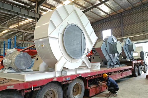
- The Core Problem: The "Fire Triangle" for Explosions
- Key Standards & Regulations
- Explosion Prevention (The Ideal Approach)
- Explosion Protection (Containment & Mitigation)
- System Architecture for "High Air Flow" + "Material Handling"
- Critical Question: What is the Material & Gas?
- Vendor Selection Checklist
This is a highly specific and critical application. You are asking about a blower system used for gas delivery and material handling that requires high air flow and explosion protection.
This combination of parameters (gas + material + high flow) creates a significant explosion risk (dust explosion, gas explosion, or hybrid mixture explosion).
Here is a comprehensive breakdown of the engineering principles, standards, and equipment solutions required for this application.
The Core Problem: The "Fire Triangle" for Explosions
In your system, you have three elements present:
- Fuel: The gas being delivered and the fine particles of the material.
- Oxidizer: The high-volume air flow (oxygen).
- Ignition Source: Heat from friction (bearing failure), impact (metal on metal), static electricity (dust moving through a duct), or an electrical motor spark.
The Goal: Eliminate or isolate the Ignition Source (Prevention) OR contain/vent the explosion if it occurs (Protection).
Key Standards & Regulations
You must comply with local and international codes. The most relevant are:
- ATEX (EU): Directive 2014/34/EU (Equipment) and 1999/92/EC (Workplace).
- IECEx (International): IEC 60079 series (Gas) & IEC 80079 (Dust).
- NFPA (USA): NFPA 68 (Explosion Venting), NFPA 69 (Prevention Systems), NFPA 70 (NEC - Electrical), NFPA 654 (Combustible Dust).
- ISO: ISO 21927 (Smoke and heat control systems) - less direct but relevant for fan testing.
Your blower and its motor must be certified for the specific zone (e.g., Zone 1, Zone 2 for gas; Zone 21, Zone 22 for dust) and gas/dust group (e.g., IIA, IIB, IIC; or Group G for dust).
Explosion Prevention (The Ideal Approach)
This aims to stop ignition from happening.
A. The Blower Design (The Rotating Assembly)
This is the most dangerous part. Standard fans create sparks.
- Material of Construction:
- Non-sparking Materials: Use Aluminum Bronze or Stainless Steel (304/316) for the impeller and housing. Avoid carbon steel-on-steel contact.
- Coating: For corrosive gases, consider Halar (ECTFE) or Rilsan (Polyamide 11) coatings on the impeller and housing.
- Impeller Design:
- Radial Tip (Paddle Wheel): Best for high flow and material handling. Strong, but prone to dust build-up on blades.
- Backward Curved: Good for efficiency and lower tip speeds, reducing friction.
- Open Impeller: Less prone to clogging with sticky materials.
- Tolerance (Critical): The clearance between the impeller tip and the housing must be larger than the largest particle being handled. A tight tolerance (like in a clean air fan) will cause frictional sparking.
- Shaft Seal: Use a Dynamic Gas Seal (DGS) or a Labyrinth Seal to prevent gas leakage along the shaft into the motor bearing housing.
- Bearing Housing:
- Shaft Grounding Rings: Essential for dissipating static charge from the rotor.
- Bearing Temperature Monitoring: PT100 RTDs (Resistance Temperature Detectors) wired to a safety shutdown relay. High temp = imminent bearing failure (an ignition source).
B. The Motor
- Certification: Must be ATEX/IECEx certified for the specific gas/dust group.
- For Gas: EEx d (Flameproof) or EEx e (Increased Safety).
- For Dust: Motor must be rated to prevent dust ingress (IP66 minimum) and limit surface temperature.
- Voltage & Frequency: VFD (Variable Frequency Drive) is common for high flow control, but the VFD must also be certified explosion-proof for the zone (or located outside the hazardous area).
C. The Piping & Ductwork
- Grounding & Bonding (Crucial): The entire system (fan housing, ductwork, supports) must be bonded to a dedicated grounding rod. Resistance to ground should be < 10 ohms (often < 1 ohm for flammable gases). This prevents static charge accumulation.
- Velocity Control: For material handling, maintain a minimum transport velocity (e.g., 15-20 m/s for plastic pellets) to prevent material settling in the duct. Settling creates a fuel bed. Maximum velocity is limited to prevent erosion.
- Flexible Connectors: Use non-metallic, conductive flexible connectors at the blower inlet/outlet to isolate vibration but maintain electrical continuity.
Explosion Protection (Containment & Mitigation)
Even with perfect prevention, assume an explosion can happen. You need hardware to manage it.
A. Explosion Isolation (The Most Important Part)
An explosion in the blower should not propagate back into the process or forward into the delivery system.
- Flame Arrestors:
- Installed on the inlet and outlet piping.
- Crimped Ribbon Type: For specific gases (like hydrogen, methane).
- Perforated Plate Type: For general gases.
- Deflagration Flame Arrestor: Must stop the flame and cool the gases below ignition temperature. Must be certified for the gas group (IIA, IIB, IIC).
- Check Valve (Backdraft Damper): A mechanical valve that closes instantly if pressure reverses, isolating the blower from a downstream explosion.
- Chemical Isolation: A high-speed injector (e.g., sodium bicarbonate) triggered by a flame detector within < 1 millisecond. This blocks the explosion path.
B. Explosion Relief (Venting)
If the blower housing ruptures, the explosion must go somewhere safe (not into the plant).
- Rupture Disc (Bursting Panel):
- Location: Mounted directly on the blower housing or on the ductwork near the blower.
- Calibration: Set to burst at a pressure below the blower housing's MAWP (Maximum Allowable Working Pressure) but well above normal operating pressure.
- Venting Duct: A pipe from the rupture disc to the outside of the building (safe location). This is mandatory; you cannot vent an explosion into a plant room.
- Size: Calculated per NFPA 68 or EN 14491 based on blower volume, gas/dust Kst (deflagration index), and venting duct length.
C. Explosion Suppression
- High-Speed Injection System:
- Detectors: Pressure sensors or flame detectors (UV/IR) mounted on the blower housing.
- Control Panel: Processes the signal.
- Suppressant Tanks: Contain high-pressure nitrogen or argon propellant.
- Chemical Agent: Sodium bicarbonate or water mist.
- Action: Upon detection (within 1-2 milliseconds), the control panel fires a chemical agent into the blower housing, extinguishing the explosion before it reaches destructive pressure.
System Architecture for "High Air Flow" + "Material Handling"
For this specific combination, you need a Positive Displacement (PD) Blower (like a Roots-type or rotary lobe) or a High-Pressure Centrifugal Fan.
Here is a typical safe system layout:
- Feed Hopper: Grounded.
- Rotary Valve (Air Lock): Essential to prevent backflow of gas/explosion. It acts as a dust barrier and a pressure barrier.
- Inlet Flame Arrestor: Prevents flame from entering the hopper.
- Blower Unit (Housing):
- Non-sparking impeller.
- Rupture disc (vented outside).
- Bearing temp sensors.
- Pressure sensors.
- Grounding stud.
- Motor: Explosion-proof, direct-drive (no belts - belts are a static hazard) via a flexible coupling.
- Discharge Piping:
- Check valve.
- Outlet flame arrestor.
- Flow meter (optional).
- Control Panel:
- Monitors bearing temps, vibration, pressure differential, and connects to the suppression system (if installed).
- Interlock: If the blower shuts down, the rotary valve and material supply must also shut down.
Critical Question: What is the Material & Gas?
- If it's a flammable gas (e.g., Hydrogen, Methane, Ethylene): The margin for error is zero. You must use a PD blower with a hermetic seal (canned motor) or a direct drive, sealed motor. The motor must be certified for Zone 1 or 2 as per the specific gas group (IIC is the most dangerous). A flame arrestor is non-negotiable.
- If it's a combustible dust (e.g., Flour, Wood Dust, Metal Powder): The primary risk is dust explosion (Kst). You need a rupture disc of a specific size (Kst-dependent). The blower must be conductive and grounded to prevent static. The impeller must have a large clearance.
- If it's both (Hybrid Mixture): This is the most dangerous scenario. The following requirements are additive. You need both gas and dust explosion protection systems. The Kst and gas group are combined in the design.
Vendor Selection Checklist
When buying a blower for this application, you must ask the vendor for these explicit guarantees:
- Certification: "Is the complete blower unit (fan + motor + accessories) ATEX/IECEx certified for the zone and gas/dust group I specified?"
- Materials: "What material is the impeller? Are all contact surfaces non-sparking?"
- Grounding: "Is a dedicated grounding stud provided on the housing, and is the shaft ground with a conducting ring?"
- Testing: "Has the blower been type-tested with a dust or gas explosion? Do you have a Kst rating for the housing?"
- Seal: "What shaft seal is used to prevent gas/material leakage into the motor bearing?"
Final Warning: Do not attempt to modify a standard blower. You need a unit purpose-built for this hazardous duty. One spark from an aluminum impeller rubbing against a steel housing can cause a devastating explosion. The cost of a certified, explosion-protected blower is a fraction of the cost of a plant explosion.





