
This article's table of contents introduction:
- The Hazard Context: Why Explosion Proof is Essential
- Key Design Features of an Explosion-Proof Fan
- Explosion Protection Systems (Beyond the Fan)
- Sizing and Selection Parameters (for Energy Efficiency)
- Standards and Certifications
- Maintenance & Operational Checklist
- Summary Recommendation
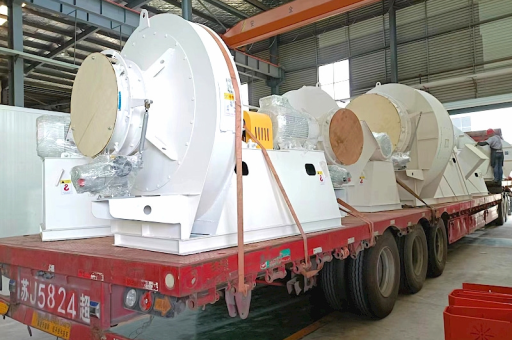
This is a critical topic combining industrial process safety, mechanical engineering, and explosion protection standards. An explosion-proof fan for a Lime Rotary Kiln flue gas system is not just a standard fan; it is specifically engineered to handle hazardous conditions.
Here is a comprehensive breakdown of the requirements, design considerations, and standards for an Industrial Energy Efficiency Lime Rotary Kiln Flue Gas Fan that is Explosion Proof.
The Hazard Context: Why Explosion Proof is Essential
Before selecting a fan, you must understand the specific risks in the Lime Kiln flue gas path:
- Combustible Gases (CO/H₂): Rotary kilns use fuel (coal, petcoke, natural gas, biomass). Incomplete combustion, especially during startup, shutdown, or process upsets, can produce high concentrations of Carbon Monoxide (CO) and Hydrogen (H₂) . These are explosive in specific mixtures with air.
- Combustible Dust (Lime/Carbon): Despite being a "clean" product, the flue gas contains fine calcined lime dust (CaO/CaCO₃) and unburned carbon particles (fly ash) . Under specific conditions (fine particle size, high temperature, presence of an ignition source), these can form a combustible dust cloud.
- High Temperature: Flue gas temperatures exiting a lime kiln can range from 180°C to 400°C (356°F to 752°F) , depending on the heat recovery system (e.g., preheater, cooler). High temperature lowers the flash point of any potential gases.
- Oxygen Content: The flue gas typically contains 3-10% residual oxygen, which is sufficient to support an explosion if a fuel source and ignition source are present.
Key Risk: A fan spark (from friction, static electricity, or mechanical failure) or a hot surface can act as an ignition source for a gas or dust cloud, causing a devastating explosion.
Key Design Features of an Explosion-Proof Fan
To mitigate the above risks, the fan must be designed to:
- Prevent Ignition (Primary Protection)
- Contain an Internal Explosion (Secondary Protection)
- Manage Spark Risk (Tertiary Protection)
Here are the critical features:
A. Motor and Electrical (The Core)
- Certification: The motor must carry an ATEX (Europe) or IECEx (International) or UL/CSA (North America) certification for the specific gas/dust group and temperature class.
- Gas Group: Typically IIA (propane, CO) or IIB (ethylene, hydrogen).
- Temperature Class: T3 (200°C max surface temp) or T2 (300°C) – MUST be lower than the auto-ignition temperature of the gases present.
- Explosion-Proof Enclosure (Ex d): The motor casing is designed to withstand an internal explosion and prevent the flame from escaping to the surrounding atmosphere. The flame path (gaps) is precisely machined to cool escaping gases below ignition temperature.
- Non-Sparking Motor Fan: The internal cooling fan on the motor shaft is made of non-sparking material (e.g., bronze, aluminum, or conductive plastic).
B. Mechanical Construction (The Fan Housing and Impeller)
- Material:
- Impeller: Ideally Stainless Steel (e.g., 316L) or aluminum-bronze to prevent sparks. For highly corrosive flue gas (containing SOx/NOx), stainless steel is mandatory.
- Housing: Carbon steel with a corrosion-resistant lining (e.g., epoxy, rubber, or high-alumina ceramic) if the gas is acidic from condensation.
- Spark-Tight Construction (Shaft Seal): The shaft penetration through the housing is a critical potential spark source.
- Labyrinth seal or double mechanical seal with a nitrogen purge.
- Gland packing with a continuous inert gas (N₂) purge to prevent gas leakage and friction sparking.
- Non-Sparking Internal Components:
- All internal fasteners (bolts, screws) must be captive and made of non-sparking material.
- Shaft grounding brushes to dissipate static electricity buildup from the rotating impeller.
- Reduced Clearance: The gap between the impeller tip and the housing is minimized (typically < 1mm) to prevent mechanical contact (rubbing) which generates heat and sparks.
C. Energy Efficiency Features (The "Energy Efficiency" part)
An explosion-proof fan does not have to be inefficient. In fact, modern designs use advanced aerodynamics to minimize energy consumption:
- High-Efficiency Impellers: Backward-curved airfoil (BC) blades instead of radial blades. BC impellers achieve 85-92% static efficiency vs. 60-70% for radial designs. This reduces motor power consumption and heat generation.
- Variable Frequency Drive (VFD): A VFD allows the fan to match the exact required airflow (process demand), avoiding throttling losses. CAUTION: A line reactor or sine-wave filter is required between the VFD and the explosion-proof motor to prevent high-frequency voltage spikes that could damage the motor insulation or create arc-over risk.
- Wear-Resistant Coatings: Applying tungsten carbide or ceramic wear tiles to the impeller and housing increases lifespan, reducing maintenance downtime and energy waste caused by inefficiencies from wear.
Explosion Protection Systems (Beyond the Fan)
The fan itself is rarely the only protection. You must also consider the system:
- Explosion Relief Panel: The fan housing should have a spring-loaded or burst-panel door on the discharge side. This panel is designed to open at a low overpressure (e.g., 0.5 bar) to vent the explosion outside (to a safe area), preventing the housing from rupturing.
- Isolation Dampers: Explosion-proof isolation dampers should be installed on the inlet and/or outlet of the fan. These close automatically within milliseconds of detecting a flame or pressure rise, preventing the explosion from propagating into the kiln or the stack. They are often triple-lobed or louvers.
- Inerting (N₂ Purge): A continuous small flow of nitrogen (N₂) into the fan housing can reduce the oxygen concentration below the Limiting Oxygen Concentration (LOC) for the dust/gas mixture, making an explosion impossible.
Sizing and Selection Parameters (for Energy Efficiency)
To optimize energy efficiency, you must precisely calculate the fan duty:
| Parameter | Typical Value for Lime Kiln | Why it Matters for Energy & Safety |
|---|---|---|
| Flow (m³/hr or ACFM) | Calculated from kiln production rate & excess air | Oversizing wastes power; undersizing causes process upset and CO generation. |
| Pressure (mmWC or inWG) | 500 - 1500 mmWC (20-60 inWG) | High pressure = high power. Use low-pressure drop ductwork/scrubbers to reduce fan power. |
| Gas Temperature | 180°C - 280°C (post-preheater/cooler) | A 10°C drop in gas temperature reduces fan power by ~3%. Use efficient heat exchangers. |
| Dust Loading (g/Nm³) | 5 - 30 g/Nm³ | High dust erodes impeller. Use low-dust design (e.g., pre-chamber or wear liners) to maintain efficiency. |
Standards and Certifications
- North America: NFPA 68 (Explosion Venting), NFPA 69 (Explosion Prevention Systems), UL 1004-1 (Rotating Electrical Machines), CSA C22.2 No. 145.
- Europe/International: ATEX Directive 2014/34/EU (Equipment), IEC 60079-0 (General Requirements), IEC 60079-1 (Flameproof Enclosures), IEC 60079-2 (Pressurization), EN 14460 (Explosion resistant equipment).
Maintenance & Operational Checklist
- Weekly: Visual inspection of shaft seal for leaks. Check bearing temperature (should be below 85°C).
- Monthly: Check for abnormal vibration (indicates imbalance or bearing wear). Inspect explosion relief panel for tightness.
- Quarterly: Test explosion isolation dampers for full closure.
- Annually: Internal inspection of impeller for corrosion/erosion. Verify grounding brush contact.
Summary Recommendation
For an Industrial Energy Efficiency Lime Rotary Kiln Flue Gas Fan that is Explosion Proof:
- Specify:
- Backward-Curved Airfoil (BC) Impeller in 316L Stainless Steel.
- ATEX/IECEx Ex d IIB T3 motor (or local equivalent).
- Double mechanical shaft seal with N₂ purge.
- Shaft grounding system.
- Integral explosion relief panel (sized per NFPA 68).
- VFD with sine-wave filter for maximum energy savings.
- Avoid:
- Radial blade impellers (poor efficiency).
- Open drip-proof (ODP) motors (not explosion proof).
- Carbon steel impellers (spark risk, corrosion).
- Operating the fan below the Minimum Continuous Stable Flow (MCSF) – this causes surge and vibration.
Final Note: Always work a Process Safety Engineer and a fan manufacturer certified for ATEX/IECEx or UL/CSA to verify the fan selection matches the specific gas/dust composition, temperature, and pressure of your kiln system. A mistake here can be catastrophic.





