
This article's table of contents introduction:
- Primary Function
- Types of Fans Used
- Critical Challenges (The "Dirty End")
- Key Design Specifications & Materials
- Operational Best Practices
- Relationship to Other Systems
- Summary Table
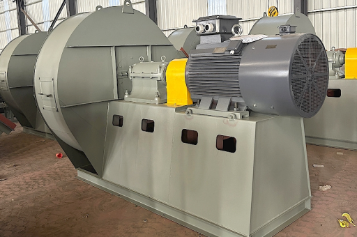
The Kiln Head Exhaust Fan (often called the Cooler Exhaust Fan, Clinker Cooler Fan, or ID Fan for the cooler) is a critical piece of equipment in the cement manufacturing process. It is located at the discharge end of the rotary kiln, between the kiln outlet and the clinker cooler.
Here is a detailed breakdown of its function, types, challenges, and best practices.
Primary Function
The fan’s core purpose is to extract hot, dust-laden air from the clinker cooler before it escapes into the atmosphere or the kiln.
- Cooling: It creates a negative pressure (suction) inside the clinker cooler, drawing ambient air through the hot clinker bed. This rapidly quenches the clinker from ~1400°C to ~100°C.
- Heat Recovery: The hot air pulled by this fan is typically sent to:
- The Rotary Kiln (as secondary combustion air).
- The Precalciner (as tertiary combustion air).
- A Waste Heat Recovery (WHR) system to generate electricity.
- Emissions Control: By pulling the air, it prevents hot gases and dust from "puffing" back out of the kiln hood into the plant environment.
Types of Fans Used
Depending on the cooler design (Grate, Planetary, Rotary), the installation varies, but the most common type is:
- Centrifugal Fan (Radial or Backward-Inclined):
- Radial Blade: Very robust, handles high dust loads. Typically used for the primary cooler exhaust.
- Backward-Inclined (BIC): More efficient, used for cleaner air streams (e.g., after a baghouse or ESP).
- Induced Draft (ID) Fan:
- This is the most common nomenclature. It pulls the air after the cooler, creating suction.
Critical Challenges (The "Dirty End")
The kiln head fan operates in one of the harshest environments in the plant. Key problems include:
| Challenge | Cause | Effect |
|---|---|---|
| Abrasive Wear | Hot clinker dust (SiO₂, Al₂O₃) at high velocity | Erosion of blades, housing, and ducting. Impeller imbalance. |
| High Temperature | Air can reach 300°C – 450°C (570°F – 840°F) | Thermal expansion, warping of blades, bearing failure. Risk of structural failure. |
| Thermal Shock | Sudden cold air ingress or clinker bed collapse | Rapid cooling causes metal fatigue and cracking of the impeller. |
| Corrosion | Condensation of acidic gases (SOₓ, NOₓ) when fan cools down below dew point | Pitting and corrosion of fan components, especially in winter. |
| Material Build-up | Sticky dust (e.g., Alkali salts) | Out-of-balance vibration, reduced efficiency, risk of "dust firing" in extreme cases. |
Key Design Specifications & Materials
- Blades: Often made of Hardox or chrome-molybdenum steel with abrasion-resistant cladding (e.g., ceramic tiles or weld-on hardfacing).
- Shaft & Bearings: Water-cooled bearing housings to manage conductive heat transfer. Use of high-temperature grease or oil circulation.
- Housing: Thick steel plate with external stiffeners. Often lined with castable refractory or ceramic liners in the inlet area.
- Variable Speed Drive (VSD): Almost mandatory. The fan speed is modulated via a VFD (Variable Frequency Drive) or hydraulic coupling to precisely control the negative pressure and cooling air volume.
- Without a VSD, a fixed-speed fan with heavy damper plates is used, which is far less efficient for process control.
Operational Best Practices
To maximize fan life (target: 12–18 months between major overhauls in harsh conditions):
- Pre-Heating: Before starting, slowly rotate the fan (cracking the damper) to warm it up. Sudden introduction of hot gas into a cold fan causes rapid thermal expansion and imbalance.
- Dust Separation: Use a Multicyclone (Dust Collector) before the fan to remove the coarse, abrasive dust. The fan located after a baghouse or ESP handles much cleaner gas.
- Vibration Monitoring: Install continuous vibration probes (API 670 compliant) on the bearing housings. Vibration is the #1 indicator of blade wear or build-up.
- Gas Cooling: If the cooler is overheating, inject water spray into the duct to cool the gas before the fan (avoiding condensation).
- Balancing: Perform on-site dynamic balancing. A slight weight imbalance due to uneven wear can amplify vibration and destroy bearings.
Relationship to Other Systems
- Kiln ID Fan: The kiln head fan is secondary to the main Kiln Induced Draft (ID) Fan (at the kiln inlet/preheater tower). The kiln head fan handles the cooler area, while the main kiln ID fan handles the preheater and rotary kiln itself.
- Cooler Airflow: The fan must work in coordination with the cooler's grate drives and under-grate fans. If the cooler pushes too much air, the head fan may struggle to pull it away, leading to "puffing."
Summary Table
| Feature | Detail |
|---|---|
| Location | Between Clinker Cooler and Stack/Heat Recovery System |
| Gas Temp | 250°C – 400°C (typical) |
| Dust Load | Very High (20 – 80 g/Nm³ without multicyclone) |
| Primary Control | Negative pressure at Kiln Hood / Cooler |
| Common Failure | Blade erosion, bearing failure, out-of-balance |
| Key Engineering | Abrasion resistance, thermal stability, VSD control |
In short: The kiln head exhaust fan is the pressure regulator for the clinker cooler. If it fails or is poorly maintained, the entire clinker production process can be crippled due to overheating, poor cooling, or environmental dust emissions.





